Imf-102 interface module frame wiring, Imf-102 interface module frame wiring -30 – Clear-Com Eclipse-Omega User Manual
Page 60
Clear-Com Communication Systems
Eclipse Matrix Installation Instruction Manual
4 - 3 0
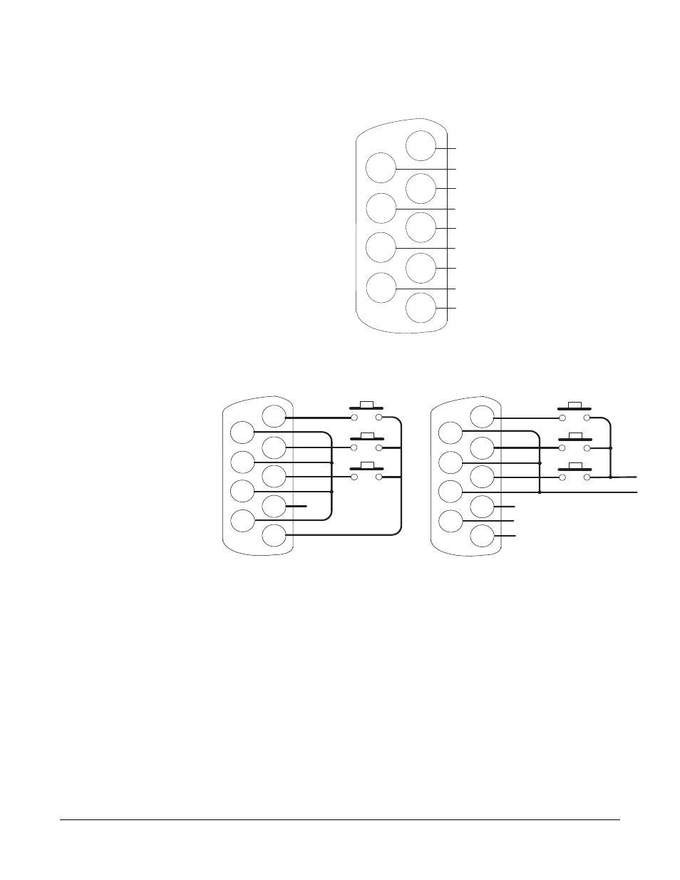
Figure 4-21: GPI-6 Interface DB-9M Connector Pinout
Figure 4-22: GPI-6 Application Examples
Figure 4-21 and Figure 4-22 show how to connect switches or contacts
using the power source provided by the GPI-6 module or powering
switches from external sources. Each input can be wired to be isolated
from each other as a further variation.
IMF-102 Interface Module Frame Wiring
The wiring of a GPI-6 interface that is placed in an IMF-102 interface
frame is the same as the wiring for a GPI-6 interface placed in an
IMF-3 interface frame. The only difference is that an IMF-102 interface
frame houses only two interfaces, and they are mounted horizontally
rather than vertically in the frame.
Figure 2-1 and Figure 2-2 in Chapter 2 illustrate the differences
between these interface frames.
1
2
9
8
7
6
5
4
3
#2/5 Input A
#3/6 Input A
Ground
#1/4 Input A
#1/4 Input B
#2/5 Input B
Ground
Power Source
GPI-6 I/O DB 9M
#3/6 Input B
1
2
9
8
7
6
5
4
3
X
1
2
9
8
7
6
5
4
3
X
X
X
GPI-6 I/O DB-9M
GPI-6 I/O DB-9M