Wiring the matrix to general purpose inputs, Wiring the matrix to general purpose inputs -12 – Clear-Com Eclipse-Omega User Manual
Page 42
Clear-Com Communication Systems
Eclipse Matrix Installation Instruction Manual
4 - 1 2
WIRING THE MATRIX TO GENERAL
PURPOSE INPUTS
It is possible to connect an external logic device such as an external
foot switch, a panel-mounted switch, or the logic output of some other
device to the connector labeled “GP IN” on the rear of the Eclipse
matrix. When the external logic device is activated, it sends a control
signal into the matrix to perform one of several preset functions, such
as turning an intercom panel’s microphone on or off, muting a
microphone’s output, or turning a panel’s speaker off. The function to
perform and the panel upon which it is performed is configured using
the Eclipse Configuration System (ECS).
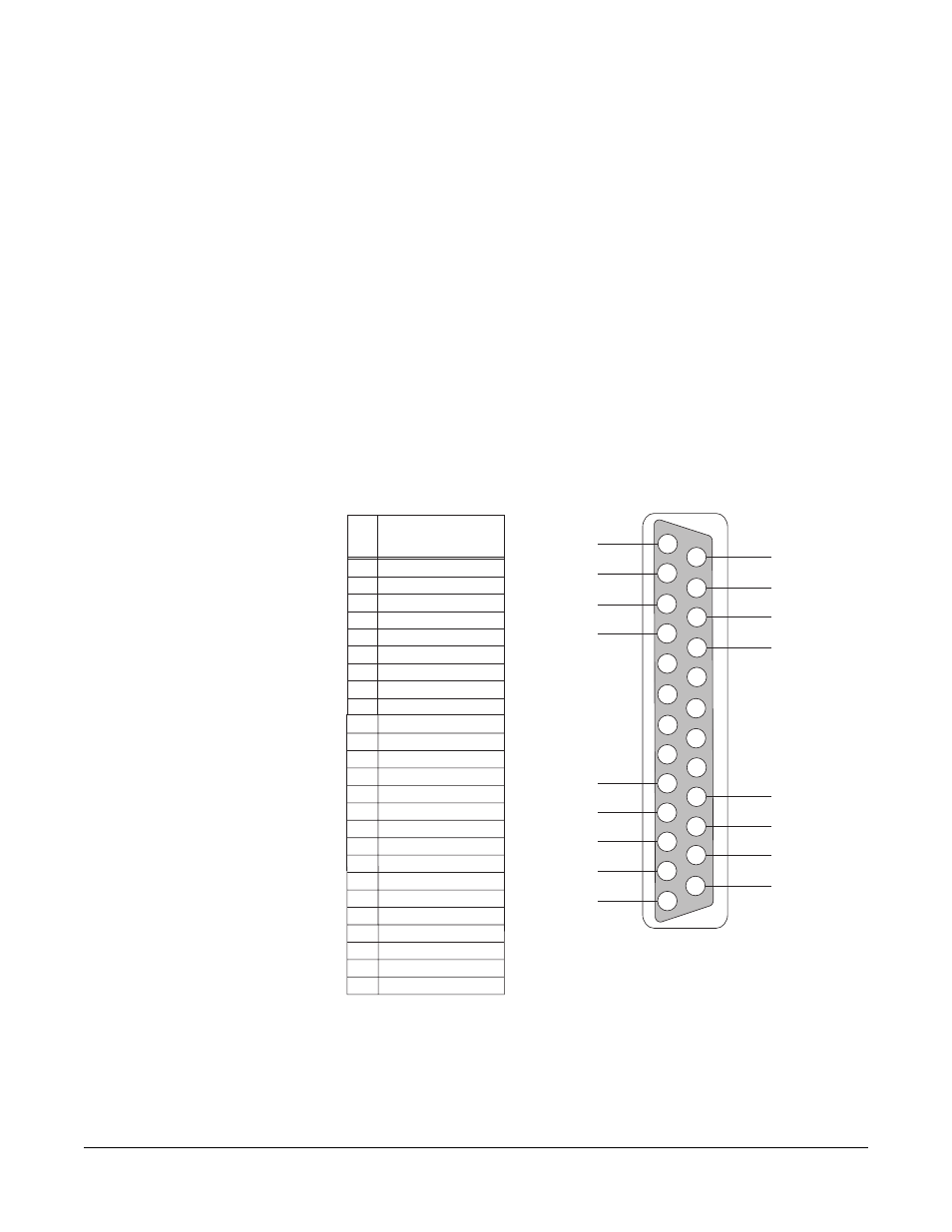
The DB-25 connector labeled “GP IN” on the rear of the Eclipse matrix
connects to eight local general-purpose inputs. Figure 4-7 shows the
pin assignments of the Eclipse general-purpose inputs connector.
Shielded cable should be used to connect General Purpose Inputs.
Figure 4-7: General-Purpose Inputs Connector Pinout
The general-purpose inputs operate in one of two modes: the
“opto-isolated” mode or the unisolated mode. The opto-isolated mode
requires the externally connected equipment to provide the current to
power the general-purpose input. The non-isolated mode does not
require that the externally connected equipment powers the
1
2
3
4
5
6
7
8
9
10
11
12
13
14
15
16
17
18
19
20
21
22
23
24
25
PIN
DESCRIPTION
1
2
3
4
Logic Input 3
Logic Input 4
N/A
N/A
N/A
N/A
Ground
Ground
Ground
Ground
Logic Input 5
Logic Input 6
Logic Input 7
Logic Input 8
N/A
5
6
7
8
9
10
11
12
13
14
16
17
18
19
20
21
22
23
24
25
15
N/A
N/A
N/A
Voltage In+
Ground
Ground
Ground
Ground
Ground
V IN+
V IN+
V IN–
V IN–
Ground
DB-25 Female Connector
Logic Input 1
Logic Input 2
Voltage In+
Voltage In-
Voltage In-
Logic Input 1
Logic Input 2
Logic Input 3
Logic Input 4
Logic Input 5
Logic Input 6
Logic Input 7
Logic Input 8