Connecting to the telephone line, Connecting to the telephone line -24 – Clear-Com Eclipse-Omega User Manual
Page 54
Clear-Com Communication Systems
Eclipse Matrix Installation Instruction Manual
4 - 2 4
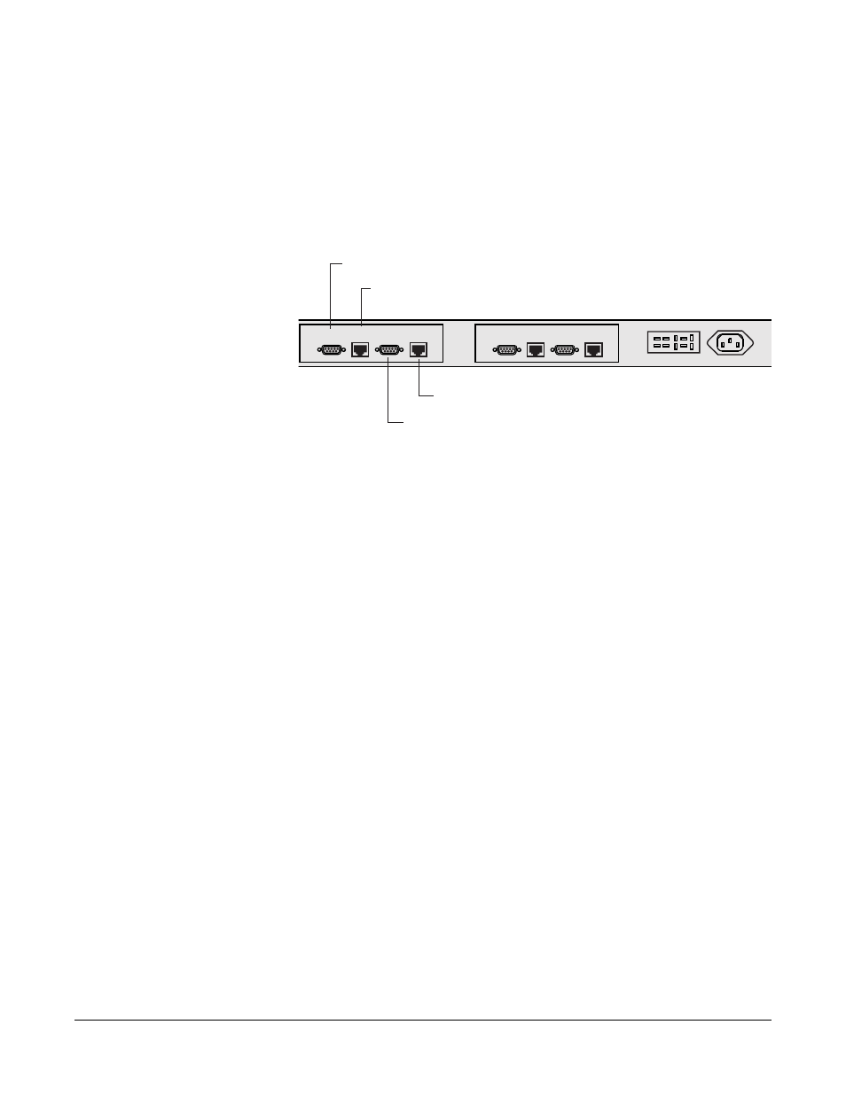
The leftmost DB-9M connector is used to connect to the first telephone
line, A. The leftmost RJ-45 connector is used to connect telephone line
A to the matrix frame. The rightmost DB-9M connector is used to
connect to the second telephone line, B. The rightmost RJ-45
connector is used to connect the telephone line B to the matrix. Figure
4-17 illustrates the wiring of one IMF-102 rear-panel assembly to a
TEL-14 interface.
Figure 4-17: Wiring an IMF-102 Rear-Panel Assembly to a TEL-14
Interface
To allow use of a common RJ-11 terminated telephone line, Clear-Com
provides two DB-9F to RJ-11 adapters (part 770025).
For internal dip-switch settings and adjustments, refer to the TEL-14
manual (part 810308Z).
Connecting to the Telephone Line
Connecting the telephone line can be accomplished with one of two
methods. One method is to use the RJ-11 to DB-9F adapters supplied
by Clear-Com with the TEL-14 interface. The second method is to
directly wire each telephone line to a DB-9F connector using the
pinouts in Figure 4-18, which shows the wiring diagram of the adapter.
CH.A
Matrix
CH.A
I/O
CH.B
Matrix
CH.B
I/O
CH.A
Marix
CH.A
I/O
CH.B
Matrix
CH.B
I/O
Connects to the first telephone line, A.
Connects telephone line A to the matrix.
Connects to the second telephone line, B.
Connects telephone line B to the matrix.