Non-isolated mode, Non-isolated mode -14 – Clear-Com Eclipse-Omega User Manual
Page 44
Clear-Com Communication Systems
Eclipse Matrix Installation Instruction Manual
4 - 1 4
NON-ISOLATED MODE
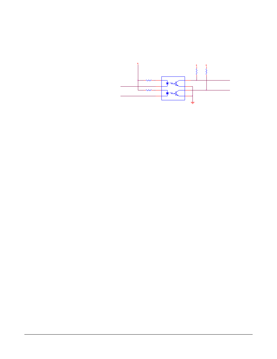
Figure 4-9 shows the non-isolated connection.
Figure 4-9: Non-Isolated Connection to Eclipse GPI Connector
To cause an input to detect an active signal, current must flow from the
relevant input pin.
The external device should draw no current to cause an inactive input
and at least 5 mA to cause an active input. The opto-isolator drive line
contains a 1.5 kOhm resistor to limit the current through the
opto-isolator. Therefore the input pins can be connected directly to a
ground pin to cause an active input.
The voltage level at the external input pin should not be allowed to go
below ground or above +6 with respect to ground.
INPUT 1
EXTERNAL INPUT 2
INPUT 2
R29 1.5K
R30
1.5K
U
MOCD207-M
1
3
2
4
8
7
6
5
EXTERNAL INPUT 1
R
33K2
+3V3
R
33K2
+3V3
+3V3