Wiring, Internal settings and adjustments, Connection to the telephone line – Clear-Com TEL-14 User Manual
Page 17
T E L - 1 4 T W O - C H A N N E L T E L E P H O N E I N T E R F A C E
2 - 3
WIRING
TEL-14 INTERFACE WIRING FOR AN IMF-3 INTERFACE FRAME
The TEL-14 line A circuit is connected to the matrix through the RJ-45
connector on the interface rear-panel assembly that the TEL-14 is connected to.
The DB-9M connector immediately adjacent to the RJ-45 is used to connect to
the telephone line. Similarly, the second RJ-45 and DB-9M connectors connect
the TEL-14 Line B circuit. Clear-Com provides DB-9F to RJ-11 adapters (CC#
770025) that allow the use of common RJ-11 telephone jacks and cords.
Warning:
The TEL-14 works with POTS (Plain Old Telephone Service) CO
(Central
Office) lines. Analog station lines in some PABXs are not
compatible.
Internal Settings and Adjustments
For internal option switch settings and adjustments, refer to the “Setup” section
in this chapter.
Connection To The Telephone Line
Connecting the telephone line can be accomplished with two methods. One is to
use the RJ-11 to DB-9M adapters supplied by Clear-Com (CC#770025) with
the TEL-14 interface. The second method is to directly wire each telephone line
to a DB-9 connector using the pinouts in Figure 2-1.
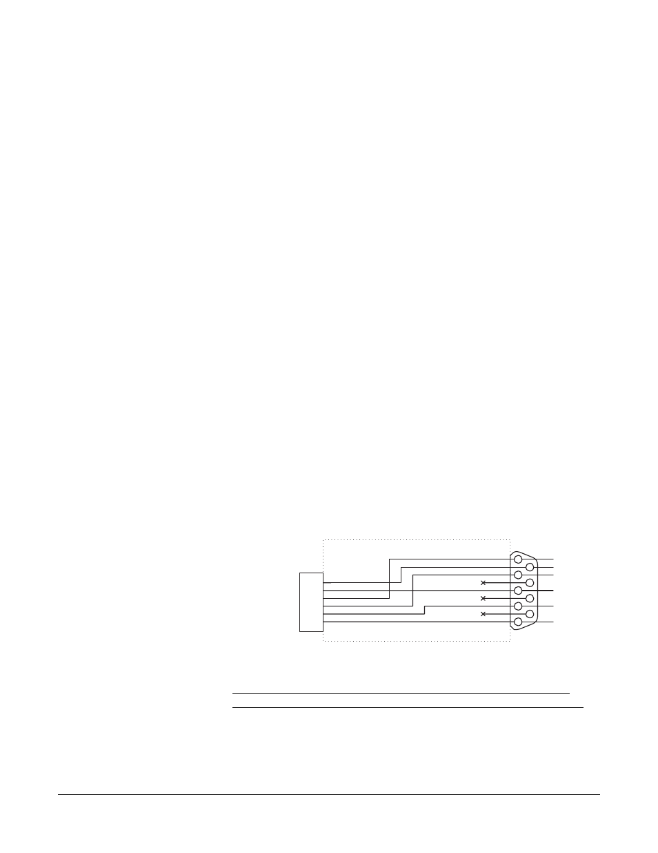
Note the Clear-Com #770020 adapter, which may be alternately supplied, does
not have the wiring to pins 1 and 6 of the RJ-11 connector. If it is necessary to
use a series-connected telephone set with the TEL-14, contact the Service
Department to obtain a CC#770025 adapter instead. Figure 2-1 shows the
wiring diagram of the adapter for one line.
Figure 2-1: RJ-11 to DB-9 Adapter for TEL-14 Interface
The phone line must be an outside (POTS) line directly connected to the
telephone company central office, and isolated from in-house phone systems. A
standard telephone can be installed in parallel with this line if desired, but it
should not be used while the TEL-14 is offhook. When the TEL-14 is
automatically adjusting its sidetone null, all additional standard telephones must
be "on-hook".
1
2
3
4
5
6
1
2
3
4
5
6
7
8
9
RJ-11 TO DB-9F ADAPTER
Clear-Com Part # 770025
PHONE (BLU)
RELAY (YEL)
LINE (GRN)
LINE (RED)
RELAY (BLK)
PHONE (GRA)
RJ-11 to
Telephone Line
DB-9F to
TEL-14
LINE
PHONE
LINE
RELAY
RELAY
PHONE