Iv. startup, Caution – Cashco 988-MB User Manual
Page 3
3
IOM-988/989-BODY
C. Removal From Piping System:
1. Care should be taken in removal of separable
fl anged units. Run wire in 180° crossing pattern
through bolt holes to prevent fl anges from coming
loose during handling.
IV. STARTUP
A. General:
1. Ensure that the Model 988/989 unit has been
prop er ly ad just ed and calibrated, including the
positioner if in stalled.
2. Recommend startup to be in a “manual” mode.
This pro ce dure assumes double block (iso la tion)
and bypass valves for the “control valve sta tion”.
See Figure 1.
3. Start with either of the two block valves closed,
with the oth er open. The bypass valve should be
closed. Pressurize sys tem if possible/practical.
4. Back out the airset’s adjusting screw until loose.
5. Turn on air supply pressure.
6. Adjust the air supply airset (fi lter-regulator) to the
prop er lev el as indicated as follows:
Bench Setting
Airset Output
psig (Barg)
psig (Barg)
5–15 (.34–1.0)
20 (1.4)
15–60 (1.0–4.1)
75 (5.2)
7. Place loop controller into “manual” mode. Vary
set ting from minimum – mid-range – max i mum
SIG out put. Observe re sponse of con trol valve unit
to these chang es of in put SIG. The valve should
fully stroke at the vari a tion from min i mum SIG to
max i mum SIG; the mid-range SIG should have the
valve stem travel at/near 1/2 open.
8. Confi rm that action of controller and positioner
– direct or reverse – are pro duc ing the desired re-
sponse in the con trol unit. Confi rm that the control
valve “fail” po si tion is as required.
9. Hereafter, the procedure assumes that actual fl u id
fl ow may be established. This may not be prac ti-
cal/pos si ble in all cas es; if so, vary procedure as
re quired. Always “heat” or “cool” down the system
piping SLOW LY by open ing the control valve sta-
tion by pass valve in small increments.
10. With one of the control valve station block valves
still closed, and the loop controller still in “manual”
mode, open by pass valve and vary fl ow rate man u-
al ly to observe the response of the con trol ler and
control valve unit to geth er.
11. Attempt to develop manual control of the loop by
open ing/closing the manual bypass as re quired,
or by manually con trol ling mainstream fl ow as
re quired.
12. When the control valve is partially open, slowly
crack open the closed block valve while si mul ta-
neous ly closing the bypass valve. Continue this
pro ce dure until the bypass is closed and the block
valves are both fully open. The system is still un-
der “man u al” mode control, but all fl ow is pass ing
through the control valve.
13. Vary controller “manual” SIG output until match ing
the “au to mat ic” SIG output, then change the mode
of the controller over to “automatic”. The loop will
ex pe ri ence a minimum of upset conditions, and will
be in au to matic control.
CAUTION
DO NOT WALK AWAY AND LEAVE A MANUALLY CON-
TROLLED CONTROL VALVE UNATTENDED!
SECTION IV
CAUTION
Exhibit care in handling fl anged units to prevent sep a ra ble
fl ang es from coming loose, falling to fl oor and smashing
feet/toes.
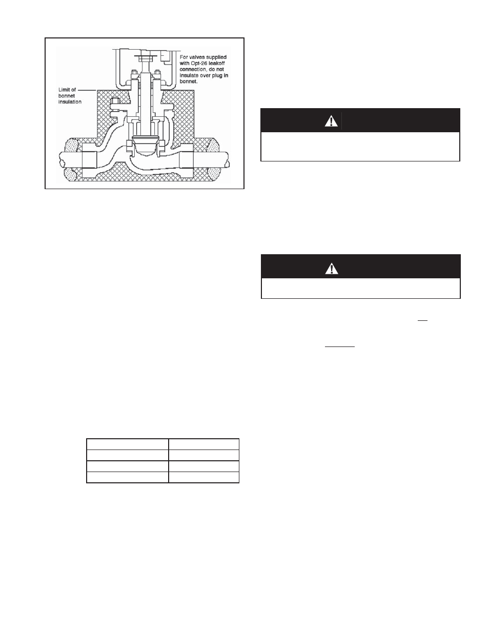
Figure 2: Body Insulation