Cashco 988-MB User Manual
Page 13
13
IOM-988/989-BODY
VI. CALIBRATION
A. General:
1. This section only covers cal i bra tion of the
control valve with Actuator Models C27/C53.
2. Positioner,
if
in
stalled, requires ref er ence to
the spe cifi c positioner mod el IOM for prop er
cal i bra tion pro ce dure.
3. All indicated items numbers that are with
re spect to IOM-C27-C53 will be in pa ren-
the sis and un der scored; i.e. (20); those that
reference the po si tion er IOM will be in double
paranthesis; i.e. ((AP)). All item numbers that
are with respect to this IOM-988/989 are not
un der scored; i.e. (3).
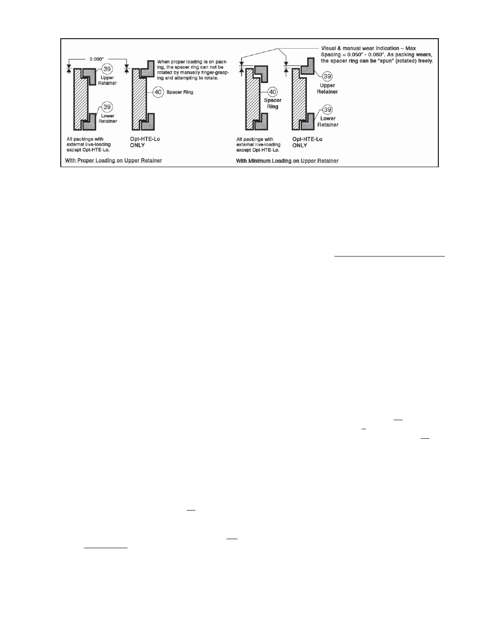
Figure 11: Dimensionals for Proper Packing Load
G. External Live-Loaded Packing Adjustment:
1. There are two types of indicators for determining
“pack ing wear” –
a. Ability to “freely spin” the spacer rings (40).
b. Measure the spacing between the upper re-
tain ers (39) spacer rings (40) (see Fig. 11).
NOTE: Regardless of live loaded packing design, all
use the same method for obtaining the proper pre-load
to new or used packing.
2. To properly tighten packing, grasp spacer ring
(40) be tween the thumb and forefi nger at points
approximately 180° from each oth er.
a. Tighten packing stud nuts (15) in 1/2 revolu-
tion in cre ments, al ter nat ing from one nut to
the other, while attempting to rotate the space
rings (40).
b. Once spacer rings (40) can no longer be
ro tat ed by the fi n gers, attempt to “even”
the op po site packing nut (15) so that the
upper re tain ers (39) are level, then add 1/2
rev o lu tion to each pack ing nut. Adjustment
completed.
3. If the spacing between the upper retainers (39)
and spac er rings (40) are used as visual indicator,
the spac ing should not ex ceed 0.060" (1.5 mm)
(ap prox i mate ly 1/16"). When this level of “packing
wear” is in di cat ed, adjustment per Step 2. above
is re quired.
4. Packing (6) adjustment can be made at any time.
NOTE: If packing (6) live-load is set too high, the
pack ing will act as non-live-loaded, jammed packing.
Ex cess actuator thrust will be required and packing
wear will be accelerated.
SECTION VI
B. Procedure - Reverse Action, ATO-FC:
1. Reference the name plate (40) at tached to
the ac tu a tor yoke (3). De ter mine the bench
set ting of the in stalled range springs (10) from
the name plate; i.e. 5-15 psig (.34 -1.0 Barg),
or 15-60 psig (1-4.1 Barg).
2. Connect a temporary air supply with an in-line
ad just able airset regulator and gauge to the
lower actuator con nec tion. See Section IV. A.
6. for appropriate supply pressure. DO NOT
LOAD with any air pressure at this point.
3. To determine when stem/plug (3) begins to
lift out of the seat, touch the stem above the
packing studs with one fi nger. (Stem will be-
gin to move when actuator pressure exceeds
the spring load.)