Cashco C-BPV User Manual
Page 6
IOM-C-BPV
6
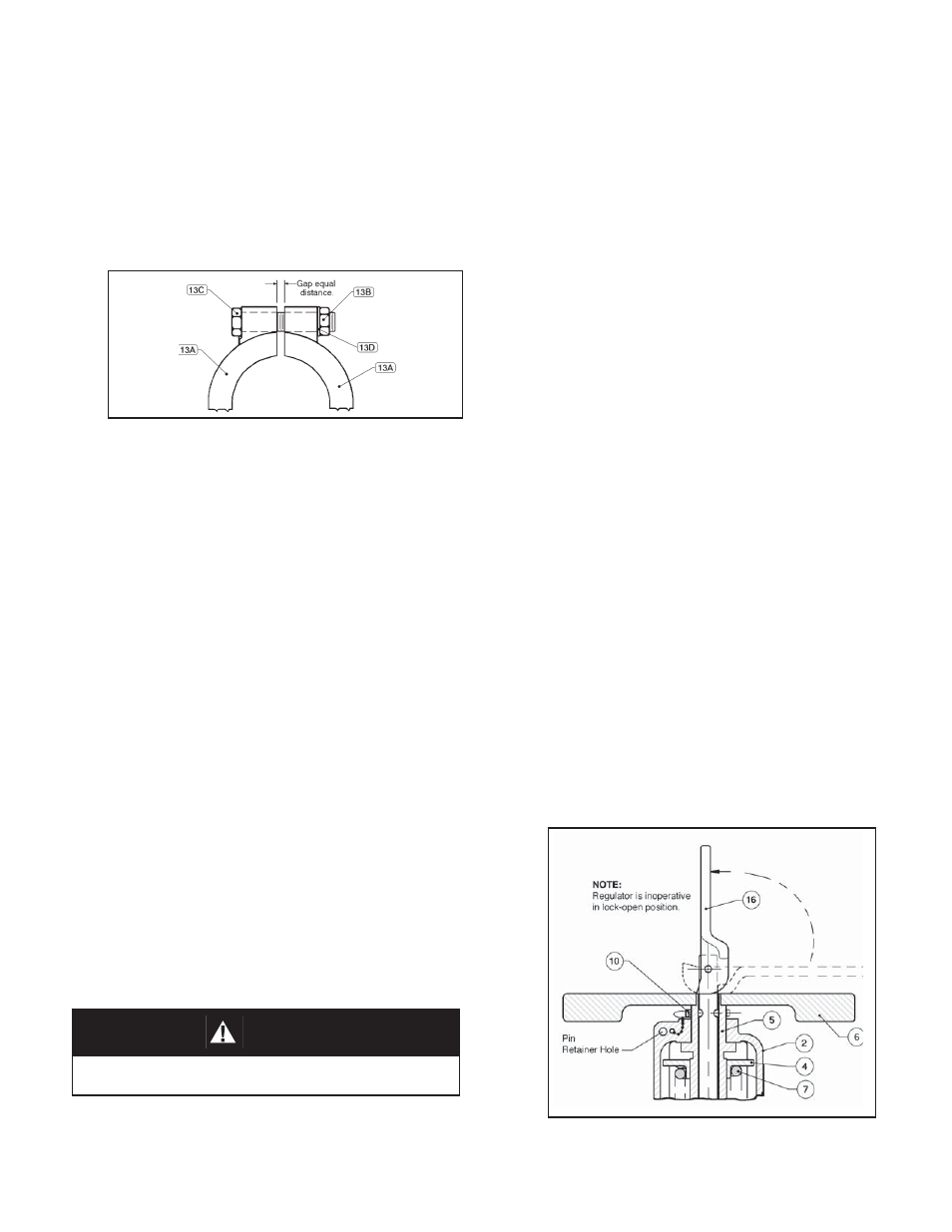
Figure 2: Spring Chamber in Lock-Open Position.
CAUTION
Owner’s cleaning solution must be compatible with regu-
lator’s trim materials.
n. Position the clamp (13) halves around
the mating fl anges of the body (1) and
the spring chamber (2). Insert clamp
bolts (13C), wash ers (13D) and tighten
clamp nuts (13B) in alternating pattern.
The clamp should be tightened to ap-
proximately 4 to 6 ft-lbs. (NOTE: Gap
be tween clamp (13A) halves should be
equal in size.
VII.CLEANING PROCEDURE
A. Pre-Sanitation:
1. Owner should refer to owner’s operating
pro ce dures for system shutdown to include
re liev ing all system pressure.
2. Refer to Fig. 3 and 4 for item number reference ().
3. Lift lever (16) to vertical position. NOTE: Do
not change range spring (7) setting by ro tat ing
adjustment nut (6) or handle (36).
4. Remove the lock-open pin (10) from the pin
retainer hole in the spring chamber (2) and
insert it into drilled passage through the ad-
just ing screw (5). (See Fig ure 2.)
B. Sanitation:
1. Flush, drain and sanitize system in ac cor-
dance to owner’s spec i fi ca tions.
NOTE: CIP is limited to 50 psig (3.45 Barg) maximum cleaning
solution pressure at 300°F (149°C). SIP is rec om mend ed to 20
psig (1.38 Barg) sat u rat ed steam pres sure; can withstand 30
psig (2.07 Barg), but may reduce elas tomer life ex pect an cy.
C. Post-Sanitation:
1. Prior to system start-up, remove the lock-open
pin (10) from the adjusting screw (5) and insert
it into the pin retainer hole. Lower lever (16)
to horizontal position. Unit is again op er a tive
at the setpoint es tab lished prior to cleaning.
SECTION VII
o. Replace eye nut (27) on guide post (22).
Ref to Section VI B. 3b previous to recall
the number of revolutions recorded for
removal.
p. Insert spring pin (32) through eye nut (27)
and guide post (22).
q. Place collar (28), bearing plate (29) and
base slide assembly (24) over guide post
(22).
r. Position cam (16) over guide post (22)
and insert quick release pin (15) through
holes in cam and post.
s. See Section IV for start up and adjustment
of set point and Section VII for Cleaning.
Figure 1: Clamp Arrangement.