Cashco 2171 User Manual
Page 4
4
IOM-1171/2171
10. Reassemble diaphragm subassembly by
plac ing pis ton O-ring (13), diaphragm(s)
(10), pres sure plate (3) and lock washer (6)
over thread ed post of piston(12). Assure the
pres sure plate (3) is placed with curved outer
rim down next to the diaphragm (10) surface.
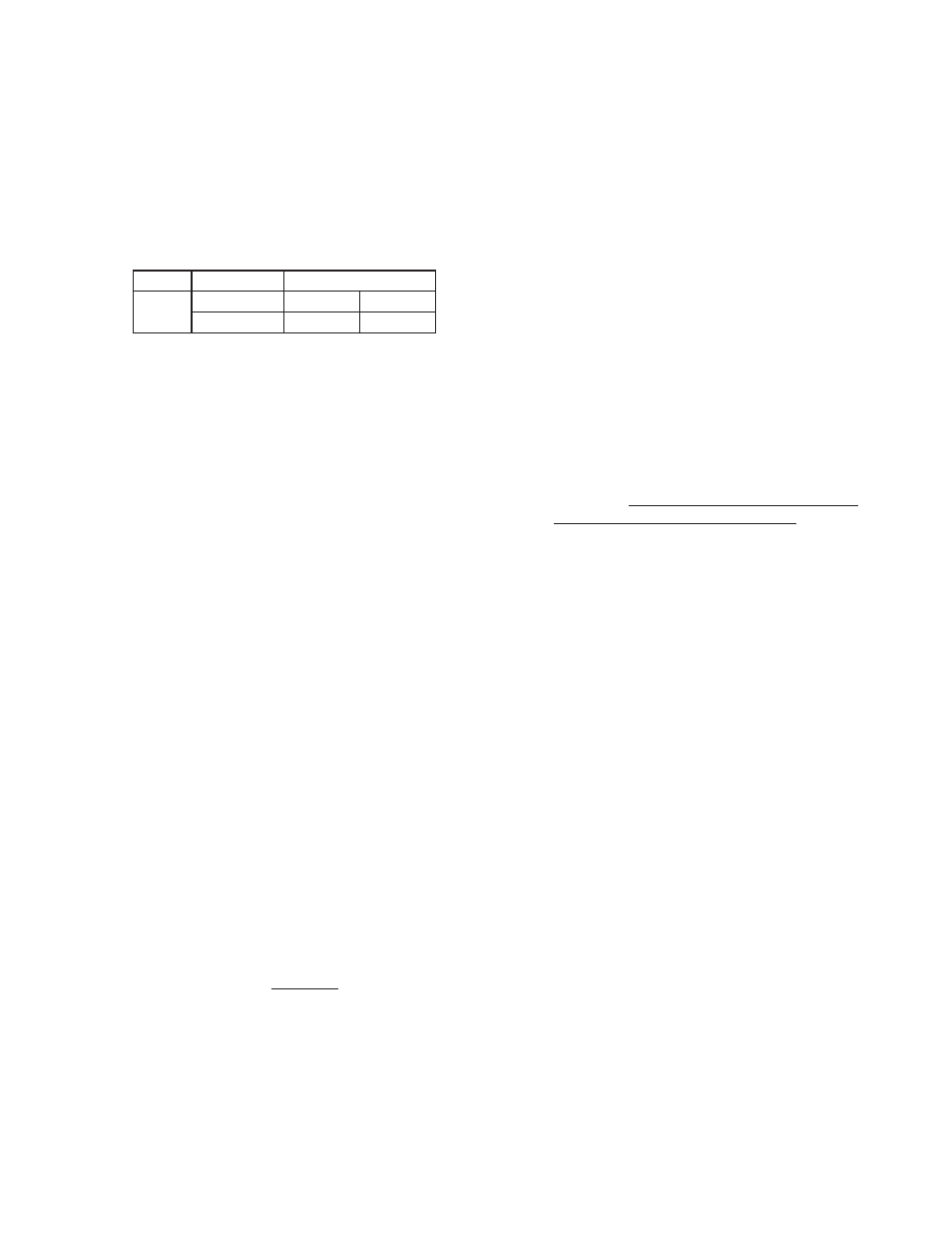
Place a thread sealant com pound similar to
Loctite #271 on the threads of the piston's
post (12) prior to tightening the pressure plate
nut (7) to the fol low ing torque values:
Sizes
Diaphragm
Torque
ALL
Metal
60 In-lbs
(6.8 N-m)
Composition
15 In-lbs
(1.7 N-m)
11. For metal diaphragm(s) (10), place dia-
phragm gas ket (11) into body (1) re cess
(none re quired for com po si tion di a phragm).
Set di a phragm sub as sem bly into the body.
12. Place the range spring (16) over the pressure
plate nut (7) of the diaphragm subassembly.
13. Place multipurpose, high temperature
grease into de pres sion of spring button (4)
where ad just ing screw bears. Set spring but-
ton (4) onto range spring (16); assure spring
button is laying fl at on spring.
14. Rotate the spring chamber (2) CW by hand
into the threaded portion of the body (1) as-
sur ing not to cross thread. NOTES: Inspect
and clean threads prior to reassembly. For
the Model 2171 apply an appropriate thread
lubricant to the spring chamber (2) threads
prior to re as sem bly to prevent seizing to-
gether with body (1). Con tin ue hand rotating
CW until fi rm ly seated against the upper
di a phragm gasket (11). Tighten the spring
chamber (2) and body (1) connection to the
following torque value: All sizes - 30-35 Ft.
lbs (41-47 Nm).
15. Reinstall ad just ing screw (5) with locknut (8)
into the spring chamber (2).
16. Pressurize body with air and spray liquid leak
de tec tor around body (1) and spring cham ber
(2) to test for leakage. Ensure that an inlet
pres sure is maintained during this leak test
of at least mid-range spring level; i.e. 20-80
psig (1.4-5.5 Barg) range spring, 50 psig (3.4
Barg) test pres sure min i mum.
C. Diaphragm Re place ment - Model 2171:
1. Procedures are the same as Model 1171.
2. For SST body (1) and SST spring chamber
(2), use thread lubricant to minimize po ten tial
of seizing threads.
D. Special Instructions for Diaphragm Re mov al:
1. If the TFE coated diaphragm is utilized on the
Model 2171, the TFE coating is the wetted
side of the diaphragm.
2. If the Option -2 handwheel is utilized, the ad-
just ing screw (5) and locknut (8) are re placed
with a handwheel (17) and lock nut (8). With
the Option-22 panel mounting w/handwheel,
the ad just ing screw and lock nut are replaced
with a handwheel (17), lock nut (8) and a panel
mounting nut (18).
3. Use only those gaskets manufactured and
sup plied by Cashco, Inc.
E. Piston Replacement:
1. Trim removal requires that diaphragm sub-
as sem bly be removed. Refer to previous
pro ce dure, Sec tion VI.B.
2. Inspect inside surface of cylinder. (NOTE:
The cylinder is an integral part of the body of
the 1171. Replace the regulator should any
damage be noted on the cylinder). If seat
shows no erosion/wear on seating surfaces,
piston (12) alone may be replaced.
3. Clean body (1) cavity. Clean all parts to be
reused. NOTE: On regulators originally sup-
plied as “oxygen clean”, Option's 1171-5-55,
2171-36-55, main te nance must include a
lev el of cleanliness equal to Cashco's clean-
ing stan dard #S-1134. Contact factory for
de tails.
4. Use special care cleaning the body (1) and
cyl in der shoulder, as this pressurized joint is
metal-to-metal with no gasket.
5. Reinstall diaphragm subassembly per Sec-
tion VI.B., Diaphragm Replacement.
6. Bench test unit for suitable operation. NOTE:
Reg u la tors are not tight shut off devices.
Even if pressure falls below setpoint, a reg u-
la tor may or may not develop bubble tight
shut off. In general, tighter shut off can be
ex pect ed with composition seat.
7. Spray liquid leak de tec tor to test for leakage
around body (1) and spring cham ber (2). Test
pressure should be the max i mum allowed by
the range spring (16) at the inlet.