Cashco 2171 User Manual
Page 3
IOM-1171/2171
3
VI. MAINTENANCE
SECTION V
V. SHUTDOWN
1. On systems with a bypass valve, and where sys-
tem pressure is to be maintained as the reg u la tor
is shut down, slowly open the by pass valve while
closing the inlet (up stream) block valve. Fully
close the inlet (upstream) block valve. (When on
bypass, the system pressure must be constantly
ob served and manually regulated. Close the
outlet (down stream) block valve.
2. If the regulator and system are to both be shut
down, slowly close the inlet (upstream) block
valve. Close the outlet (downstream) valve only
if reg u la tor re mov al is required.
SECTION VI
A. General:
1. Maintenance procedures hereinafter are
based upon removal of the regulator unit
from the pipeline where installed.
2. Owner should refer to owner's procedures for
removal, handling, cleaning and disposal of
non reuseable parts, i.e. gaskets, etc.
3. Refer to Figure 1, Model 1171 or 2171 for the
basic regulator and Figure 2, Model 1171 or
2171 for the cryogenic regulator. Blow-ups of
options and the com po si tion seat trim are on
either drawing.
B. Diaphragm Replacement - Model 1171:
1. Install the body (1) in a vise with the spring
chamber (2) oriented upwards.
3. Loosen spring chamber (2) by placing wrench
on “fl ats” and rotating CCW mak ing sure not
to use the fl ats on either side of the vent hole.
4. Remove spring chamber (2), range spring
(16), spring button (4).
5. Remove the diaphragm subassembly con-
sist ing of the pressure plate nut (7), lock
wash er (6), pressure plate (3), diaphragm
(10), piston O-ring (13) and piston (12).
NOTE: Refer to the quan tity of dia phragms
(10) in cor po rated per the bill of materials.
De pend ing on inlet pressure level, multiple
metal diaph ragms (10) may be “stacked”.
6. Loosen pressure plate nut (7) and separate
all parts (3, 6, 7, 10, 12 &13) of the diaphragm
sub as sem bly.
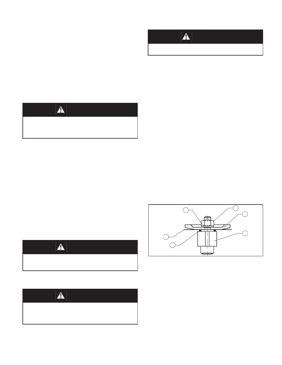
Model's 1171/2171 Diaphragm Sub as sem bly
7. Inspect pressure plate (3) to ensure no
de for ma tion due to over-pressurization. If
de formed, replace.
8. Remove diaphragm gasket (11). (If a com-
position di a phragm is used there is no di a-
phragm gasket (11).
9. Clean body (1) and di a phragm flange.
NOTE: On reg u la tors origi nally sup plied as
“oxygen clean”, Op tion s 1171-5 & -55, 2171-
36 & -55, main tenance must in clude a level of
clean li ness equal to Cash co's clean ing stan-
dard #S-1134. Con tact fac to ry for details.
2. Relax range spring (16) by turning adjusting
screw (5) CCW until removed from spring
cham ber (2).
13
10
6
7
3
12
WARNING
SYSTEM UN DER PRES SURE. Prior to performing any
maintenance, isolate the reg u la tor from the system and
relieve all pres sure. Failure to do so could result in per-
sonal injury.
CAUTION
Do not walk away and leave a bypassed regulator
unattended.
CAUTION
To prevent damage to body, use lead jaws when placing
body in a vise. Position body so that vise closes over the
side inlet connections.
WARNING
SPRING UNDER COMPRESSION. Prior to re mov ing
spring chamber, relieve spring compression by back ing
out the ad just ing screw. Failure to so so may result in
fl ying parts that could cause personal injury.