Cashco 31-N User Manual
Page 2
IOM-31-N
2
7. In placing thread sealant on pipe ends prior to
en gage ment, assure that excess material is
re moved and not allowed to enter the regulator
upon startup.
6. Clean the piping of all foreign material including
chips, welding scale, oil, grease and dirt before
in stall ing the regulator. Strainers are rec om -
mend ed.
8. Flow Direction: Install so the fl ow direction match es
the arrow cast on the regulator body.
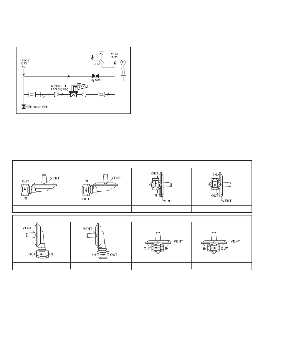
9. Refer to Figure 2. Regulator may be rotated
around the pipe axis 360°, and may be installed
in a horizontal or vertical pipeline. Four orientation/
arrangement assembly positions are standard. Ori-
ent to prevent the spring chamber vent hole from
collecting rainwater or debris. Reorient ac tu a tor
around the stem axis 360° if nec es sary.
10. Regulators are not to be direct buried un der -
ground.
11. For insulated piping systems, recommendation is
to not insulate regulator.
12. Cashco does not recommend fi eld welding on
the body of the regulator. If weld connections are
desired, specify Opt-32, extended plain end pipe
nipples.
SECTION III
up wards movement of the diaphragm due to the
P
2
pressure. As outlet pressure drops, the range
spring pushes the diaphragm down, opening the
regulator’s port via the linkage lever travel. As
outlet pressure increases, the diaphragm pushes
up against the range spring and the port closes.
Figure 1
Recommended Piping Schematic For
Pressure Re duc ing Station
Position 1
Position 2
Position 3
Position 4
FOR VERTICAL PIPING
FOR HORIZONTAL PIPING
Position 1
Position 3
Position 2
Position 4
Figure 2
III. PRINCIPLE OF OPERATION
1. Refer to internals drawings Figures 5 thru 8.
2. Internal trim movement occurs as pressure vari a-
tions register on the diaphragm. The registering
pressure is the controlled outlet pressure, P
2
, or
down stream pressure. The range spring opposes