Iom-31-n 11, External sensing option internal sensing option 44 – Cashco 31-N User Manual
Page 11
IOM-31-N
11
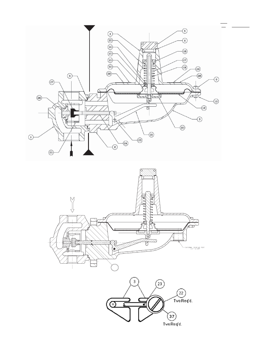
Figure 8
Partial Plan: Linkage Lever (21) Pedestals
Linkage Lever
(21) mounts be-
tween pedestals;
not shown for
clarity.
Item
No. Description
1
Body
3
Lower Case
4
Spring Chamber
5
Closing Cap
6
Gasket (Closing
Cap)
8
Gasket (Body)
9
Machine Screw
10 Nut, Hex.
11 Cap Screw
12 Diaphragm
13 Upper Diaphragm
Plate
15 Nylon Bushing
16 Washer
17 Range Spring
18 Adjustment Screw
19 Stop Post
20 Lower Diaphragm
Plate
21 Linkage Lever
22 Machine Screw
23
Linkage Pivot Pin
24 Stem
25 Nylon Loading
Ring
26 Orifi ce
27 Seat
28 Nameplate
29 Drive Screw
30 Warning Plate
32 Defl ector Ring
33 SST Loading
Ring
34
Bug Proof Vent
Plug (not shown)
37 Washer (fl at)
44 O-ring (Stem)
(Ext'l Sensing)
* DSA Diaphragm
Sub-Assembly
Pedestals
* Diaphragm Sub-Assembly (DSA) is made
up of Item Nos. 12, 13, 14, 15, 16 & 19.
Pedestal
Body Assembly (BA)
Actuator Assembly (AA)
Figure 5
1/2", 3/4" & 1' Body Sizes
External Sensing Option
Internal Sensing Option
44