Hellwig Power Lift 6097 User Manual
Page 21
559-734-7451 800-367-5480 FAX 559-734-7460
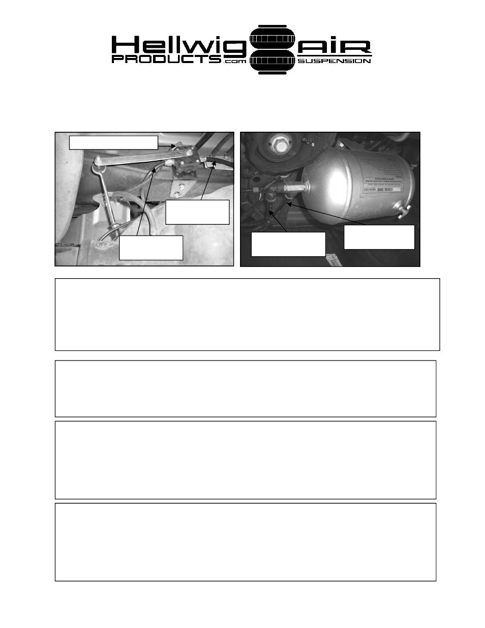
26. Connect air springs to leveling valve as shown. Loop passenger side hose over
crossmember as shown to avoid contact with exhaust pipe. Tie strap hoses as re-
quired to avoid contact with exhaust and chafing on frame. (picture shown is for
hose routing information only as vehicle shown has 6” lift installed.)
Connect to Pass
side air spring.
Connect to Driver
side air spring.
Connect to air tank. .
Connect to leveling
valve.
Connect to elbow on
relay bulkhead.
27. After all connections have been verified, install fuse in inline fuse holder, apply park
brake and start engine with shifter in park or neutral. Due to the amperage draw of the
compressor, failure to turn engine on during initial startup may drain the battery enough to
require a jump start.
28. Test system by adding air to air springs. Disconnect linkage from arm and rotate arm
up to fill air springs. Check all connections with soapy water for leaks. After the integ-
rity of the system is verified, reconnect linkage to valve. A MINIMUM OF 5-10 PSI
MUST BE MAINTAINED IN AIR SPRINGS AFTER INSTALLATION FOR WAR-
RANTY TO BE VALID. FAILURE TO KEEP MINIMUM PRESSURE IN AIR
SPRINGS WILL VOID WARRANTY
.
29. Recheck all components and test drive vehicle. Re-check all components for mount-
ing and proper torque. Check clearance to all vehicle components including suspension
components, exhaust pipe, brake lines, fuel lines, hoses, etc. Re-check installation on a
regular basis afterward. The air tank MUST be drained at least every couple of weeks to
prevent condenation buildup, FAILURE TO REGULARLY DRAIN AIR TANK WILL
VOID WARRANTY
.
6097 ( R-6097)
10/03/2007