Hellwig Power Lift 6097 User Manual
Page 12
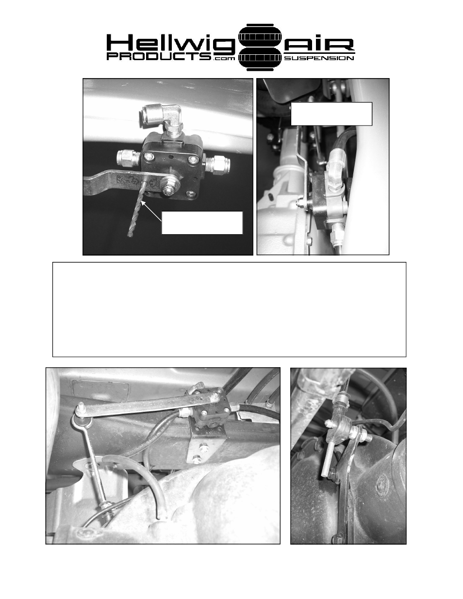
16. Assemble linkage as shown in photos and clamp leveling valve bracket to
frame crossmember in location shown so that linkage geometry matches photo.
Make sure leveling valve is as close to crossmember as possible to provide axle
clearance when suspension compresses. DO NOT drill mounting holes at this
time. Center leveling valve by inserting a 11/64” drill bit through hole in arm and
body of leveling valve. When satisfied with linkage geometry, REMOVE drill
bit.
Center lever arm on
valve with 11/64” drill
Locate valve as close to
crossmember as possi-
6097 ( R-6097)
10/03/2007
See also other documents in the category Hellwig For the car:
- Pro Series Silence (2 pages)
- Pro Series 61610 (2 pages)
- Pro Series 61901 (2 pages)
- Pro Series 61905 (2 pages)
- Pro Series Standard (2 pages)
- Load Pro Series LP 25 (2 pages)
- Load Pro Series LP 15 (1 page)
- Load Pro Series 9640 (1 page)
- Load Pro Series 9655 (2 pages)
- EZ 1000 (1 page)
- EZ 991 (1 page)
- Front Helper Spring 14114 (1 page)
- Front Helper Spring 14139 (2 pages)
- Helper Spring 820 (1 page)
- Helper Spring 979 (3 pages)
- Helper Spring 982 (2 pages)
- Helper Spring 1250 (1 page)
- Helper Spring 1251 (1 page)
- Helper Spring 1510 (2 pages)
- Helper Spring 1515 (1 page)
- Helper Spring 1520 (2 pages)
- Helper Spring 1555 (1 page)
- Helper Spring 1560 (1 page)
- Helper Spring 1565 (1 page)
- Helper Spring 1901 (3 pages)
- Helper Spring 1902 (2 pages)
- Helper Spring 1906 (1 page)
- Air 6005 (6 pages)
- Sway Bar 5909 (3 pages)
- Air 6006 (7 pages)
- Air 6012 (8 pages)
- Air 6014 (7 pages)
- Air 6016 (7 pages)
- Air 6090 (21 pages)
- Air 6091 (9 pages)
- Air 6102 (7 pages)
- Air 6106 (6 pages)
- Air 6108 (8 pages)
- Air 6107 (6 pages)
- Air 6110 (9 pages)
- Air 6111 (8 pages)
- Air 6118 (7 pages)
- Air 6150 (6 pages)
- Air 6154 (6 pages)
- Air 6210 (6 pages)