Hellwig Power Lift 6097 User Manual
Page 19
559-734-7451 800-367-5480 FAX 559-734-7460
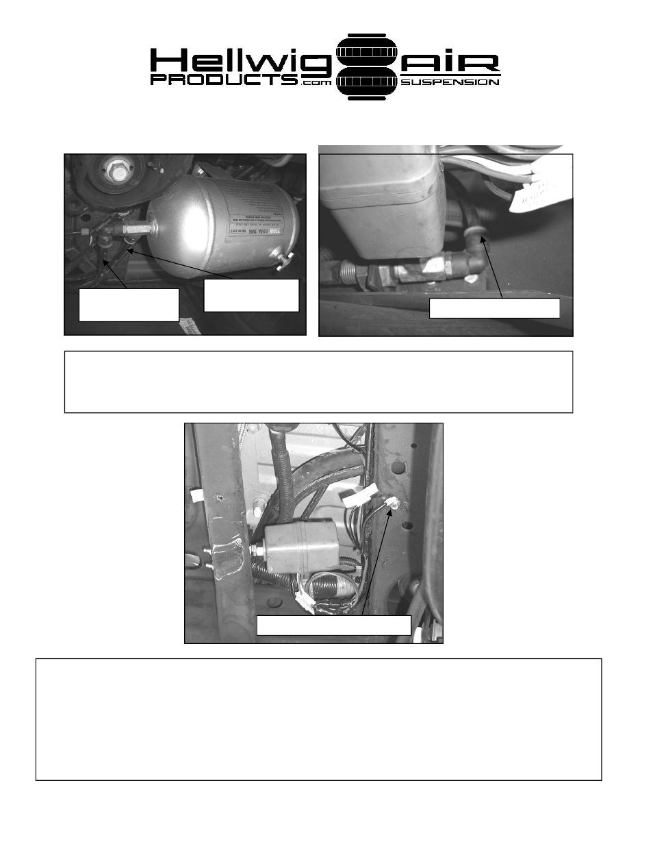
24. Connect fitting on relay bulkhead to 3/8” fitting on tank using 3/8” nylon tub-
ing as shown. Make sure hose will not be damaged by rubbing on any frame
mounted components.
25. Route 12 ga and 16 ga electrical wires from compressor to engine compartment along
driver’s side frame rail. Make sure to fasten wires securely to existing wire harness.
Follow
plumbing and wiring diagram for connection of leveling valve, compressor, and relay.
Take care
when routing air and electrical lines that they will not be crimped or chafed during installation or
use. Deviation from the electrical diagram and failure to use an inline fuse holder (supplied) will
void warranty. DO NOT install fuse in inline fuse holder until all connections and circuits are veri-
fied to be completed correctly.
Tank connection to relay
Connect to leveling
valve.
Connect to elbow on
relay bulkhead.
Ground relay and pump to frame
6097 ( R-6097)
10/03/2007
- Pro Series Silence (2 pages)
- Pro Series 61610 (2 pages)
- Pro Series 61901 (2 pages)
- Pro Series 61905 (2 pages)
- Pro Series Standard (2 pages)
- Load Pro Series LP 25 (2 pages)
- Load Pro Series LP 15 (1 page)
- Load Pro Series 9640 (1 page)
- Load Pro Series 9655 (2 pages)
- EZ 1000 (1 page)
- EZ 991 (1 page)
- Front Helper Spring 14114 (1 page)
- Front Helper Spring 14139 (2 pages)
- Helper Spring 820 (1 page)
- Helper Spring 979 (3 pages)
- Helper Spring 982 (2 pages)
- Helper Spring 1250 (1 page)
- Helper Spring 1251 (1 page)
- Helper Spring 1510 (2 pages)
- Helper Spring 1515 (1 page)
- Helper Spring 1520 (2 pages)
- Helper Spring 1555 (1 page)
- Helper Spring 1560 (1 page)
- Helper Spring 1565 (1 page)
- Helper Spring 1901 (3 pages)
- Helper Spring 1902 (2 pages)
- Helper Spring 1906 (1 page)
- Air 6005 (6 pages)
- Sway Bar 5909 (3 pages)
- Air 6006 (7 pages)
- Air 6012 (8 pages)
- Air 6014 (7 pages)
- Air 6016 (7 pages)
- Air 6090 (21 pages)
- Air 6091 (9 pages)
- Air 6102 (7 pages)
- Air 6106 (6 pages)
- Air 6108 (8 pages)
- Air 6107 (6 pages)
- Air 6110 (9 pages)
- Air 6111 (8 pages)
- Air 6118 (7 pages)
- Air 6150 (6 pages)
- Air 6154 (6 pages)
- Air 6210 (6 pages)