Pulse output wiring – Fluid Components International ST50 User Manual
Page 7
ST50 MASS FLOW
FLUID COMPONENTS INTERNATIONAL LLC
This page is subject to proprietary rights statement on last page
7
Doc. No. 06EN003367 Rev. D
Output and Pulse configuration setup command “V”
*Each sample period the number of pulses are calculated and output by the open collector. Any remaining fractional pulse in the calculation will be added
to the next sample. Example:
flow = 90 NCMM (= 1.5 NCMS), Pulse factor =1, sample time is 1.
after 1 second the number of calculated pulses is 1.5, pulse out is 1. Remainder = 0.5
after the next second the number of pulses is 2 (1.5+0.5), pulses out is 2. Remainder = 0
Analog out
Select 1
Select 2
Select 3
Select 4
4-20mA out1
Flow
Flow
Temp
Temp
4-20mA out 2
Temp
Flow
Flow
Temp
Pulse out
Select 1
Select 2
Select 3
Select 4
Source
pulse
pulse
Alarm0
Alarm0
set
Factor
Factor
Setpoint
Setpoint
Time
Time
sate
state
state
state
Sink
Pulse
Alarm1
Pulse
Alarm1
Factor
Setpoint
Factor
Setpoint
Time
sate
Time
sate
state
state
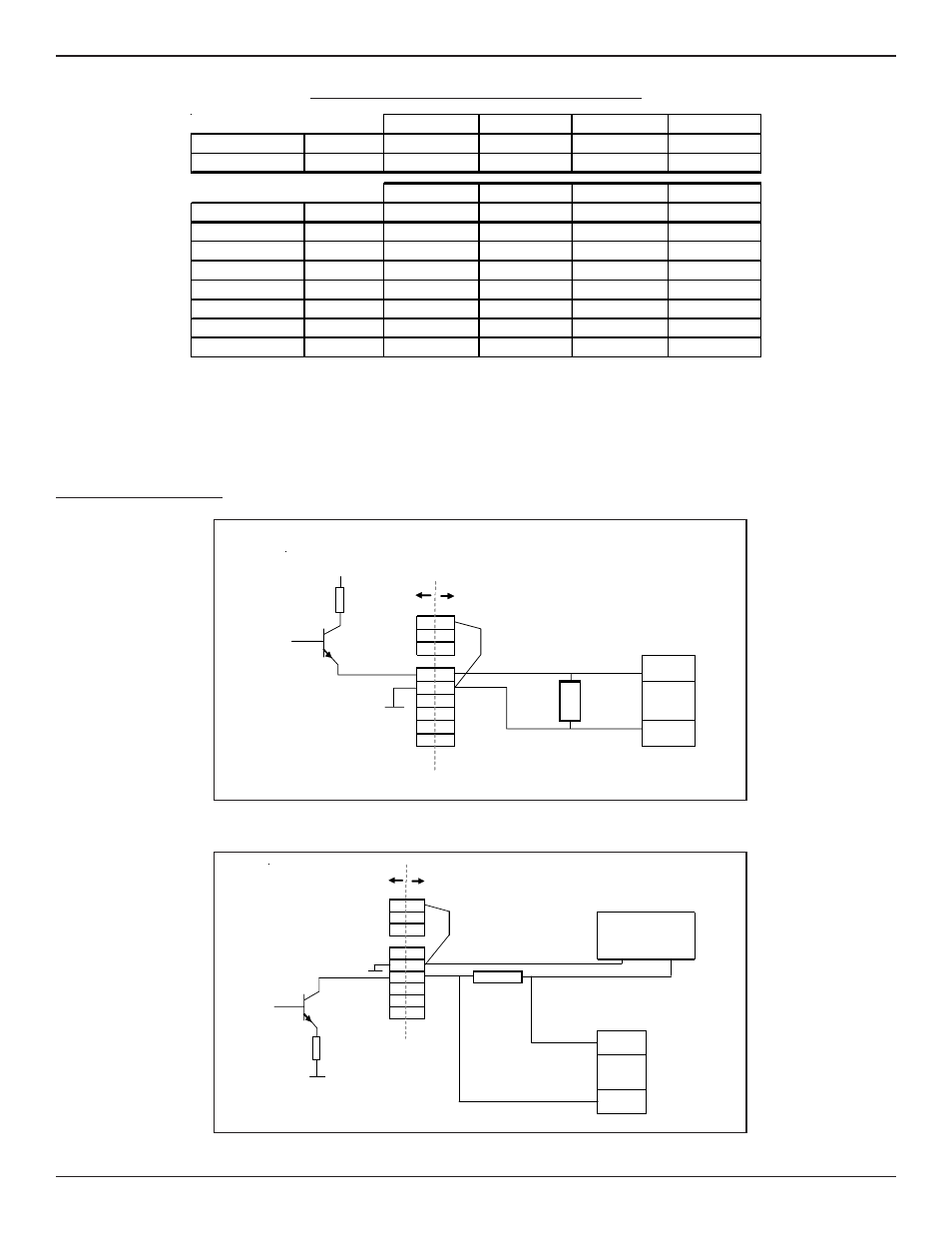
ST50 Pulse Output (Source)
ST50 Pulse Output (Sink)
FCI
customer wiring
egnd
Neut
Line
source
-
+
com
sink
10KΩ
4-20
RTN
4-20
Counter input
NPN
Com
150mA maximum
jumper
External 24-40 vdc
power Supply
15 vdc
50mA max.
FCI
customer
wiring
egnd
Neut
Counter
input
Line
NPN
source
com
10
sink
K
4-20
Ω
RTN
Com
4-20
jumper
Pulse Output Wiring