Hardware verification – Fluid Components International ST50 User Manual
Page 17
ST50 MASS FLOW
FLUID COMPONENTS INTERNATIONAL LLC
This page is subject to proprietary rights statement on last page
17
Doc. No. 06EN003367 Rev. D
Hardware Verification
Equipment Required:
Digital Multimeter
Screw Driver
The ST50 Flowmeter is comprised of 4 basic components:
1. Sensor element.
2. Customer interface circuit board
3. Control circuit assembly circuit board module.
4. Electronics enclosure.
Step 1
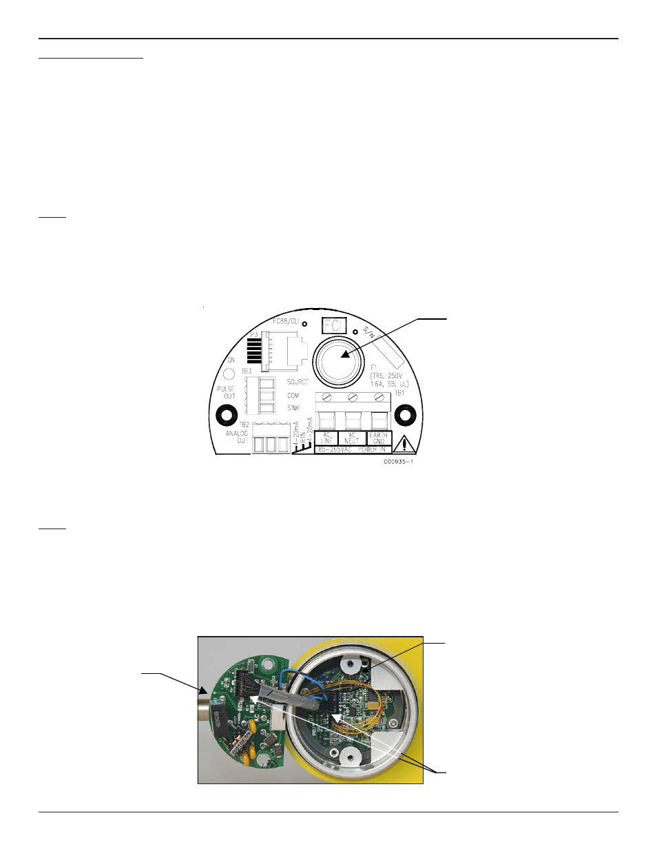
Verify fuse (F1) located on the customer interface circuit board is in normal working condition.
Remove power from the instrument. Open the electronics enclosure exposing the customer interface circuit board. This circuit
board is located under the shorter enclosure lid along with all of the power and input/output connections. Unscrew the clear cover
on the fuse and pull the fuse out of the fuse holder. Check the fuse for continuity. If fuse reads open, replace with equivalent
component (FCI part no. 019933-01), Wickmann Inc. series 374, amp code 1160, package 41.
Ac power customer interface circuit board shown. Fuse (F1) on DC power customer interface circuit board located in similar
position.
Step 2
Verify interconnecting cable from the customer interface board and the control circuit board assembly module are correctly seated
into the appropriate header.
Remove power from the instrument. Open the electronics enclosure exposing the customer interface circuit board. This circuit
board is located under the shorter enclosure lid along with all of the power and input/output connections. Remove the 2 screws
securing the interface circuit board to the electronics enclosure. Carefully lift the interface face board exposing the interconnecting
cable between the interface board and the control circuit assembly. Verify cable is seated firmly at both ends of the cable header.
Fuse (F1)
Cable Header
Interface Board
Control Circuit
Assembly