Fluid Components International ST50 User Manual
Page 18
FLUID COMPONENTS INTERNATIONAL LLC
ST50 MASS FLOW
This page is subject to proprietary rights statement on last page
18
Doc. No. 06EN003367 Rev. D
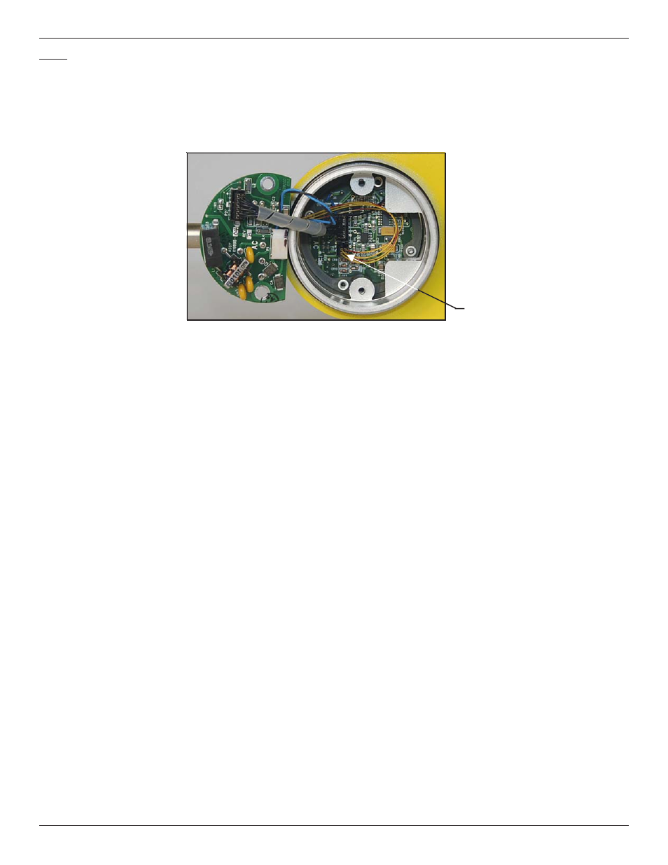
Step 3
Verify sensor element continuity and resistance.
Remove sensor element cable from the bottom of the control circuit assembly. Note that 2 of the wires have a red stripe and are
located closest to the interconnecting cable header. Using an ohm meter verify that resistance between the 2 red striped wires is
approximately 1100 ohms +/- 20. This resistance is temperature dependant. The resistance at 70 degrees F should be 1082 ohms.
Verify the resistance between the 2 natural colored wires are approximately the same.
Sensor Element Cable
See also other documents in the category Fluid Components International Equipment:
- FC88 KIT (5 pages)
- Quality Assurance Manual (94 pages)
- 8-66B_12-64B Series Manual Installation (4 pages)
- 8-66B_12-64B Series Manual Operation (2 pages)
- 8-66B_12-64B Series Manual Maintenance (2 pages)
- 8-66B_12-64B Series Manual Troubleshooting (4 pages)
- 8-66B_12-64B Series Manual Guide (4 pages)
- 8-66B_12-64B Series Manual Cover Page (10 pages)
- 8-66B_12-64B Series Manual General Information (2 pages)
- 8-66B_12-64B Series Manual Drawings (2 pages)
- 8-66B_12-64B Series Manual Glossary (2 pages)
- 8-66B_12-64B Series Manual CE Conformance (2 pages)
- FLT Series (65 pages)
- FLT93 (12 pages)
- FLT Series Rack Mount (61 pages)
- FLT93 Nuclear (58 pages)
- FR73B Manual Installation (2 pages)
- FR73B Manual Operation (2 pages)
- FR73B Manual Maintenance (2 pages)
- FR73B Manual Troubleshooting (4 pages)
- FR73B Manual Cover Page (10 pages)
- FR73B Manual General Information (2 pages)
- FR73B Manual Drawings (2 pages)
- FR73B Manual Glossary (2 pages)
- FR73B Manual Customer Service (4 pages)
- FR73B Complete Manual (20 pages)
- FS10 Button Setup Quick Guide (4 pages)
- FS10 Field Quick Setup Mode (1 page)
- FS10A (54 pages)
- LS2000 (12 pages)
- OEM MASS FLOW SWITCH (2 pages)
- RF83 Manual Customer Service (4 pages)
- RF83 Manual Glossary (2 pages)
- RF83 Manual Drawings (10 pages)
- RF83 Manual General Information (2 pages)
- RF83 Manual Cover Page (10 pages)
- RF83 Manual Installation (4 pages)
- RF83 Manual Operation (4 pages)
- RF83 Manual Maintenance (2 pages)
- RF83 Manual Troubleshooting (6 pages)
- CMB (106 pages)
- CMF Series Manual Installation of Flow Element (9 pages)
- CMF Series Manual Installation of Electronics (14 pages)
- CMF Series Manual Table of Contents (3 pages)
- CMF Series Manual Technical Data (10 pages)