Fluid Components International OEM Flow Meter User Manual
Oem mass flow meter: configuration -2a1, Installation and operation guide, Instrument wiring
Reference Sensor
OEM MASS FLOW METER: Configuration -2A1
INSTRUMENT INSTALLATION
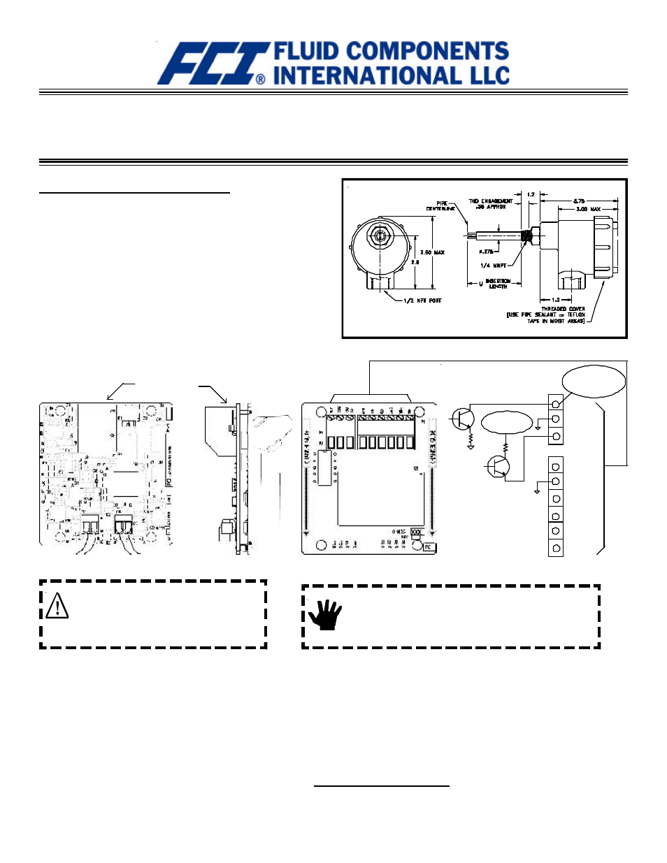
Installation Outline Diagram
The OEM Mass Flow Meter is an insertion instrument capable of measur-
ing air and gas flow in a wide range of processes. The instrument can be
top or side mounted. The process connection is male 1/4 inch NPT (or 1/2
inch NPT compression fitting). See the installation outline drawing below
for mounting dimensions.
There is an orientation mark etched onto the hexagonal surface of the
element. The flow element must be located with the orientation mark
parallel to flow. Apply an appropriate sealant to the male threads when
installing the flow element and securing enclosure cover. Tighten the
element until it is hand tight. Use a wrench to rotate the element until the
flow arrow on the hexagonal flat is in the direction and parallel to flow,
±2°. If possible, it is recommended the enclosure be located such that the
conduit port is in a downward direction to reduce the opportunitiy of
moisture collecting in the enclosure.
Installation and Operation Guide
Use the following steps to wire the instrument:
l FCI recommends installing an input power disconnect switch
and fuse near the instrument to interrupt power during
installation, maintenance, calibration, alarm selection and
troubleshooting procedures.
l Ensure the power is off before wiring the instrument.
l Conduit or other protective sheathing should be connected to
the1/2 inch port of the enclosure.
l Unscrew and remove the top cover of the instrument. Lift
the circuit board assembly by pulling up on the white plastic pull
tie wrap. The customer connections are near the top of the
circuit board. Be careful not to stress the wires that are
connected to the circuit board.
RJ11, (RS232
Connection)
Active Sensor (RED)
Instrument Wiring
Alert:
Use standard ESD (elctrostatic discharge) precautions
when handling the transmitter circuit board.
Caution:
Only qualified personnel are to wire or test this
instrument. The operator assumes all
responsibilities for safe practices while wiring or
troubleshooting.
l Connect 24 VDC input power to P1 +V IN and -V IN.
l Connect the 4-20mA output terminals as required.
l Connect pulse or alarm output if desired (source or sink mode). Refer to
specifications and setup on following pages.
l Push the board back into the enclosure and replace the top cover.
l Turn power on to operate the instrument.
Verify that the wiring is correct. Contact FCI Technical Service if problems
still persist. The telephone number is (800) 854-1993, or (760) 744-6950.
TROUBLESHOOTING
SINK
COM
SOURCE
VOUT
RET
4-20mA
Earth GND
VIN
VIN
15 VDC Output
50mA max
40 VDC max.
150mA max.
customer supplied
power source
P1
P2
Pulse or Alarm
Pulse or Alarm
+
-
This page is subject to proprietary rights statement on last page