Fluid Components International ST98 Manual Installation User Manual
Page 8
FLUID COMPONENTS, INTL
CHAPTER 2 - INSTALLATION
Model ST98 Flow Meter
2 - 8
Doc. No. 06EN003291 Rev. A
Remote Hardware Location (Option)
The outline dimensions shown in Appendix A show the physical dimensions for the proper mounting of the flow
element and transmitter electronics enclosure. Select a location for the flow transmitter within 1000 feet (310 M)
of the flow element. Pigtail flow elements can not be located more than 10 feet (3 M) from the flow transmitter.
This location should be easily accessible with enough room to unscrew the enclosure top at any time. Secure the
enclosure to a surface capable of providing support. Use appropriate hardware to secure the enclosure.
Note:
In cases where a pigtail flow element cable must be extended, a 9 position terminal strip must be used.
All 8 conductors and the shield wire must have an exclusive terminal landing for proper operation. See
Table 2-1 for the minimum wire gauge to use.
Wiring the In-Line Flow Element (Option)
Electrically the in-line flow element is the same as the model ST98 insertion flow element. Wire the instrument
using the local enclosure or remote enclosure and/or the pigtail wiring methods above.
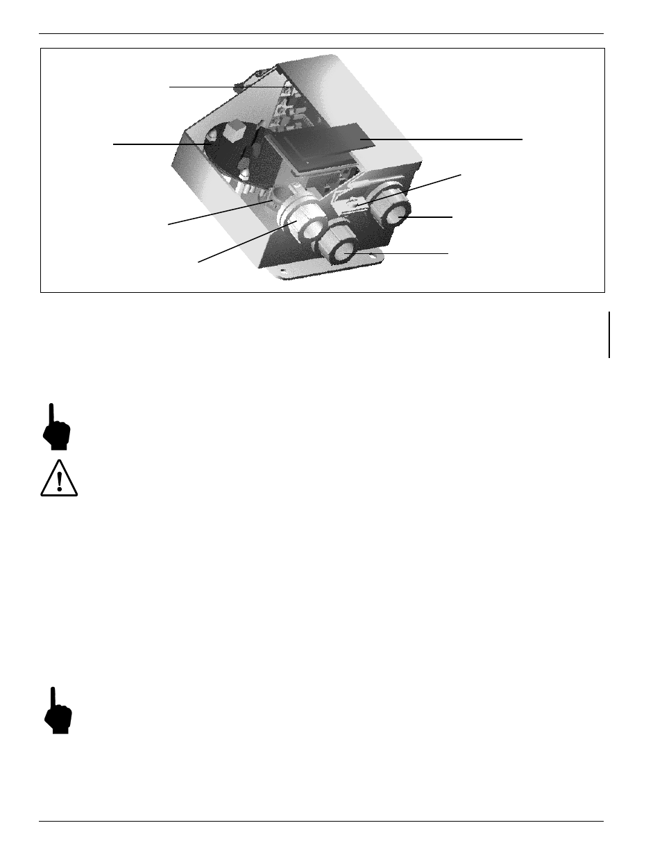
Figure 2-6. Optional Carbon Steel Enclosure
POWER
AND
SIGNAL
CONNECTION
BOARD
ELECTRONICS
3/4 INCH NPT
PORT FOR INTEGRAL
FLOW ELEMENT
3/4 INCH NPT PORT
FOR REMOTE
FLOW ELEMENT
3/4 INCH NPT PORT
POWER INPUT
OPTIONAL
DISPLAY
HOLD DOWN SCREWS
(3 PLACES)
3/4 INCH NPT PORT
SIGNAL OUTPUT
7.
Attach the power wires to Terminal Strip TS1(for AC) or TS4 (for DC) as shown in Figure 2-4. Secure the
wires going to the Terminal Strip with a cable tie, secured to the cable tie bracket on the customer connection
board.
8.
For remote instruments only, (the flow element is in a separate enclosure from the electronics):
The flow element wires should be routed through the 3/4 inch NPT port for the flow element as shown in
Figure 2-6. Connect the flow element wires to TS2 on the electronics assembly according to Figure 2-5.
Connect the cable shield to HTR RTN. Leave the other end of the shield floating.
Note:
Connecting the shield in any other way will decrease the accuracy of the instrument. See Figure 2-5
for the wiring diagram.
Caution:
Be sure a grounded wire is connected to the ground terminal (see Figure 2-4) or to the enclosure
ground screw. This is for the purpose of safety.
9.
If a wire comes loose from the instrument during installation, refer to Chapter 5 - Troubleshooting for a
complete instrument wiring diagram.
10. Close the cover and tighten the hold down screws.
11. There are enough threads on the flow element so the flow transmitter enclosure can be rotated for ease of
viewing the display LCD if the option is present. Be sure the flow arrow still points in the direction of flow
and the flat is parallel to the flow.
12. Verify proper installation. Ensure that the assemblies are secure and the wiring is correct.