Fluid Components International ST98 Manual Installation User Manual
Page 5
Doc. No. 06EN003291 Rev. A
2 - 5
Model ST98 Flow Meter
CHAPTER 2 - INSTALLATION
FLUID COMPONENTS, INTL
Make all electrical connections through the 3/4 inch NPT ports in the enclosure. Run all electrical cables through
appropriate conduit or protective sheathing.
Caution:
Ensure that all power is off before wiring any circuit.
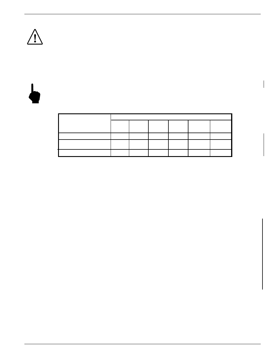
Minimum Wire Size
If the instrument is used in the remote configuration, a shielded, 8 conductor cable should be used between the
local and remote enclosure. Table 2-1 shows the smallest (maximum AWG number) copper wire that should be
used in the cable and in other wiring. Use a lower gauge of wire for less of a voltage drop. Contact FCI
concerning greater distances than those listed in the table. The sensing element cable for the remote option must
be shielded. The maximum wire size of the non-power connectors in the instrument is 16 AWG. The maximum
wire size of the power connectors in the instrument is 12 AWG.
Note:
All 8 conductors for the sensing element must be used for proper operation of the flow meter.
Table 2-1. Maximum AWG Number
Aluminum Enclosure Installation (Cylindrical Enclosure)
1.
To wire the instrument remove the customer connection cover from the instrument by loosening the Allen
head screw at the base of the cover. Unscrew the cover shown in Figure 2-3.
2.
Install conduit between the local (if used) and the remote enclosure, the power source and customer
monitoring circuits. Provide watertight hardware and apply thread sealant to all connections to prevent water
damage.
3.
Connect the milliamp and/or DC voltage output to the termination (customer connection) board as required.
Refer to Figure 2-4 for connection information.
4.
Connect the operating power to the customer termination board by removing the input wiring kit from the
strain relief bracket (see Figure 2-4 for the bracket location). This kit contains a filter bead and three cable
ties. For remote instruments only, the kit also contains 2 wire terminals for a ground wire to be placed
between the flow element enclosure and the electronics enclosure.
5.
Strip the incoming power wires to approximately 5/16 of an inch.
6.
Attach the filter bead over the safety ground wire as shown in Figure 2-4 using 2 cable ties to secure the bead
on the wire. The last cable tie should be about 3 inches from the end of the wire.
7.
Attach the power wires to Terminal Strip TS1 (for AC) or TS4 (for DC) as shown in Figure 2-4. Secure the
wires going to the Terminal Strip with a cable tie, secured to the cable tie bracket on the customer connection
board.
8.
For remote instruments only, (the flow element is in a separate enclosure from the electronics):
Loosen the Allen head screw on the electronics cover. Unscrew the cover.
Maximum Distance for AWG
Connection
Input Power
Sensing Element Cable
(Remote Instrument)
Analog Output
10 ft.
(3 m)
50 ft.
(15 m)
100 ft.
(31 m)
250 ft.
(76 m)
500 ft.
(152 m)
1000 ft.
(310 m)
24
24
18
20
18
18
16
18
24
24
24
24
16
16
16
16
16
14