Fluid Components International ST98 Manual Installation User Manual
Page 6
FLUID COMPONENTS, INTL
CHAPTER 2 - INSTALLATION
Model ST98 Flow Meter
2 - 6
Doc. No. 06EN003291 Rev. A
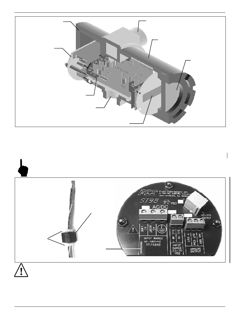
Figure 2-3. Circuit Board Placement
9.
For remote instruments only: The flow element wires should be routed through the 3/4 inch NPT port for the
flow element as shown in Figure 2-3. Connect the flow element wires to TS2 on the electronics assembly
according to Figure 2-5. Connect the cable shield to HTR RTN. Leave the other end of the shield floating.
A 14 AWG ground wire should also be routed between the enclosures (wire terminals are supplied in the kit).
Note:
Connecting the shield in any other way will decrease the accuracy of the instrument. See Figure 2-4
for the wiring diagram.
Caution:
Be sure an earth ground wire is connected to the ground terminal (see Figure 2-4). On a remote
configuration, connect an earth ground wire to the ground screw in the local enclosure. This is for
the purpose of safety.
10. If a wire comes loose from the instrument during installation, refer to Chapter 5 - Troubleshooting for a
complete instrument wiring diagram.
Figure 2-4. Customer Connection Board
POWER
AND
SIGNAL
CONNECTION
BOARD
3/4 INCH NPT PORT (2 PLACES)
OPTIONAL
DISPLAY
GLASS
3/4 INCH NPT
PORT FOR
FLOW ELEMENT
ELECTRONICS
ELECTRONICS COVER
(NO USER ACCESS
NECESSARY FOR
INTEGRAL INSTRUMENTS)
CUSTOMER
CONNECTION
COVER
OPTIONAL DISPLAY
P1
TS1
TS4
TS3
TIE DOWN
BRACKET
CABLE TIES
FERRITE BEAD