Fluid Components International ST98 Manual Installation User Manual
Page 7
Doc. No. 06EN003291 Rev. A
2 - 7
Model ST98 Flow Meter
CHAPTER 2 - INSTALLATION
FLUID COMPONENTS, INTL
Caution:
Ensure that all power is off before wiring any circuit.
Carbon Steel Enclosure Installation (6 X 6 Carbon Steel Enclosure)
1.
To wire the instrument loosen 3 cover hold down screws and open the cover. See Figure 2-6.
2.
Install conduit between the local (if used) and the remote enclosure, the power source and customer monitoring
circuits. Provide watertight hardware and apply thread sealant to all connections to prevent water damage .
3.
Connect the milliamp and/or DC voltage output to the termination (customer connection) board as required.
Refer to Figure 2-4 for connection information.
4.
Connect the operating power to the customer termination board by removing the input wiring kit from the
strain relief bracket (see Figure 2-4 for the bracket location). This kit contains a filter bead and three cable
ties. For remote instruments only, the kit also contains 2 wire terminals for a ground wire to be placed
between the flow element enclosure and the electronics enclosure.
5.
Strip the incoming power wires to approximately 5/16 of an inch.
6.
Attach the filter bead over the safety ground wire as shown in Figure 2-4 using 2 cable ties to secure the bead
on the wire. The last cable tie should be about 3 inches from the end of the wire.
11. For remote instruments only: Screw on the electronics cover and tighten the Allen head screw.
12. Screw on the customer connection cover and tighten the Allen head screw.
13. There are enough threads on the flow element so the flow transmitter enclosure can be rotated for ease of
viewing the display LCD if the option is present. Be sure the flow arrow still points in the direction of flow
and the flat is parallel to the flow.
14. Verify proper installation. Ensure that the assemblies are secure and the wiring is correct.
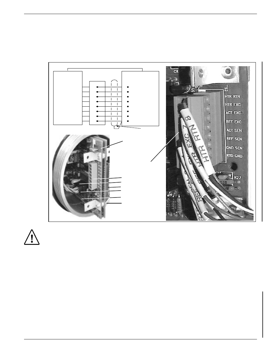
Figure 2-5. Remote Wiring Diagram
RTD GND 1
GND SEN 2
REF SEN 3
ACT SEN 4
REF EXC 5
ACT EXC 6
HTR EXC 7
HTR RTN 8
BOARD ASSY.
P/N 017749
TS2
1
2
3
4
5
6
7
8
LOCAL
ENCLOSURE
TB1
SENSOR
ELEMENT
USE 8 CONDUCTOR SHIELDED CABLE ONLY
RTD GND 1
GND SEN 2
REF SEN 3
ACT SEN 4
REF EXC 5
ACT EXC 6
HTR EXC 7
HTR RTN 8
SHIELD
14 AWG GROUND SAFETY WIRE
P5
P4
TS2 SOCKET
ENCLOSURE
P3
TP1
EPROM
TS2
PLUG