Fluid Components International ST98 Manual Operation User Manual
Page 2
FLUID COMPONENTS INTL
CHAPTER 3 - OPERATION
Model ST98 Flow Meter
3 - 2
Doc. No. 06EN003291 Rev. A
A user entry is indicated by brackets [ ] being placed around the entry. Y/N refers to Yes (Y), save or change
parameter or No (N) do not save or change parameter unless otherwise specified.
Backspaces are made using the backspace [BKSP] key.
Some entries are case sensitive between numbers and letters. Be sure the SHIFT key is pressed to indicate the
correct case. A square after the prompt caret indicates the FC88 is in lower case. A slightly raised rectangle in the
same spot indicates the FC88 is in the upper case.
It is recommended that the FC88 be plugged into the instrument before power is applied. If the FC88 is plugged in
while the instrument power is on and the FC88 does not respond, press [ENTER], if there is no response press [P],
if there is still no response Press [N].
Note:
Some entries require a pass code (942) to continue programming the instrument. The instrument will
prompt the user when this is necessary. Do not change any parameters that require this code unless there
is an absolute understanding of the instrument's operation. Incorrect changes can cause an inaccurate or
a non-operational instrument. The figures in the "Delta "R" Table would need to be re-input.
The user can not exit some routines unless all entries are completed or the power is recycled.
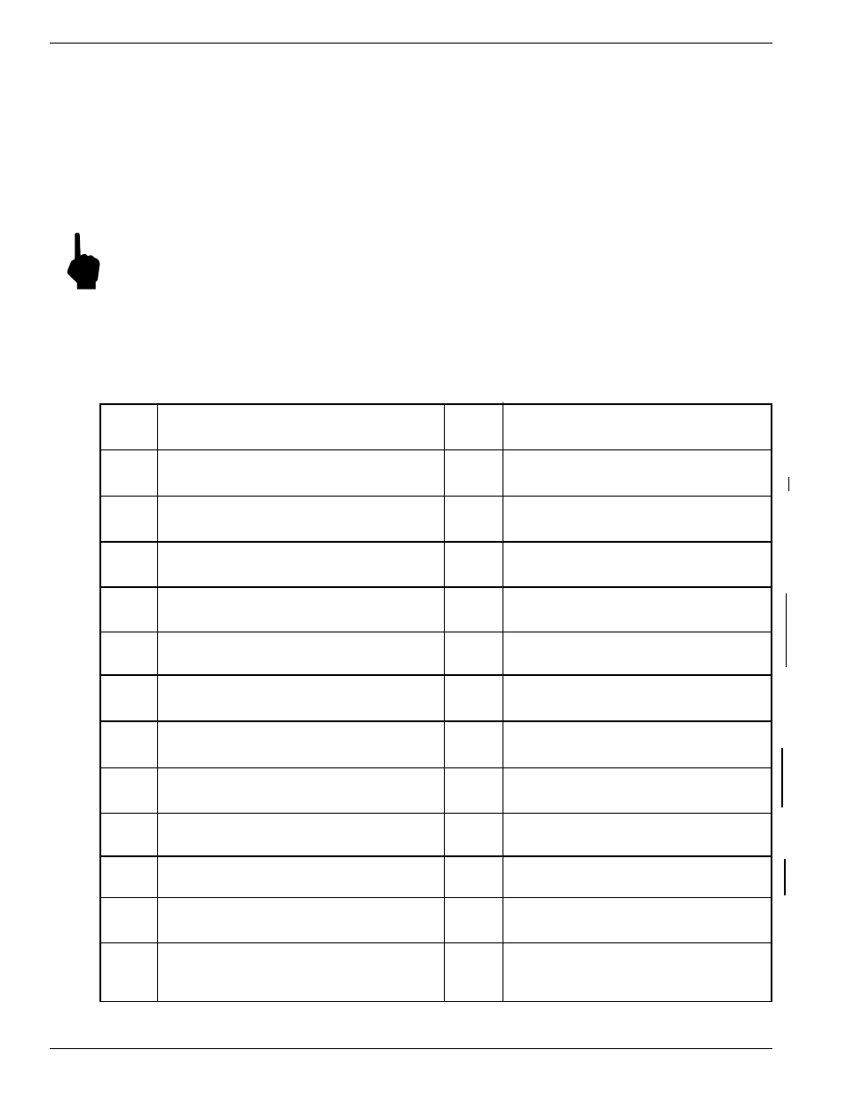
The top level of the menu is shown below. Press the large letter in the Figure 3-1 to activate a command.
N
Software Reset
Re-initialize instrument without removing power
O
Select Sensor Heater Current
HIGH (90 mA) or LOW (75 mA)
P
Re-configure FC88 Unit
Reset the FC88 hand held to ST98 format
Q
Undefined
R
Delta-R, Ref-R, CB Temp, -8/+20 V
Display Delta-R, Ref-R resistor values, etc.
S
Save/Restore USER Save and FACTORY
Calibration data saved and restored
T
Normal Operating Mode
Display flow rate, temperature, totalized flow
U
Display Total Flow Time
Total time (min) in T mode since last reset
V
NAMUR Output Fault Indicator
NAMUR flag, select fault indicator
W
Totalizer Mode
Enable totalized flow w/wo temperature
X
NAMUR Output Fault Indicator
Toggle NAMUR flag(on/off) select fault indicator
Y
Undefined
Z
Flow Units Select
Select flow units (3 English , 3 Metric)
A
Analog Input
Rotate through the 8 analog input channels
B
Sensor Balance
Balance or rebalance Flow Element
C
Calibrate Display
Display A/D Delta-R and Ref-R data values
D
Diagnostic
Check out functional conditions of the unit
E
Sensor Current Select
Displays 2.0 mA - 1k ohm
F
K-Factor
K-Factor entered by user.
G
EEPROM
PW = available when needed
EEPROM byte locations - read/ write.
H
Heater
Toggle heater circuit - OFF/ ON.
I
Output Current Adjust
Manually set output: 4-20 mA, display output load
J
Serial/Customer Numbers
Enter Serial No. and Customer Order No.
K
Constants Setup
Setup curve fit, TC parameters, and other data
L
Calibrate Outputs
Outputs - Heater Current, 4 mA, 20 mA levels.
M
Min/Max A/D Limits
Set minimum and maximum A/D limits
Figure 3-1. Menu Selections Chart