Procedure – Fluid Components International FLT Series Rack Mount User Manual
Page 14
Doc. No. 06EN003250 Rev. N/C
D - 3
FLT
Series FlexSwitch
Rack Mount
APPENDIX D - TEMP COMP
FLUID COMPONENTS INTL
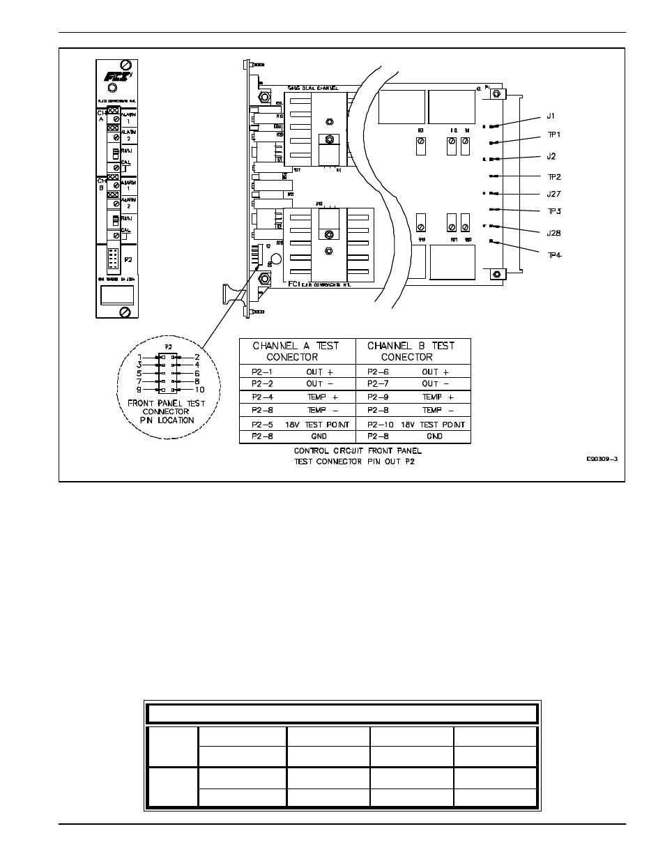
Figure D-1. Potentiometer and Test Point Locations for Temp Comp
Procedure
1.
Turn off the instrument power.
2.
Install the instrument into the pipe or a test stand where it can be calibrated. Start the process media flowing at a
normal rate. Cool the process media to the lowest temperature in the expected operating range.
3.
Disconnect the wires leading to the sensing element (ACT, REF, COM HTR, HTR). Removal of the terminal
strip from the enclosure may be necessary for access to the wires.
4.
Connect the DMM's and the power supply to the sensing element as shown in Figure D-2.
5.
Set the power supply voltage to the proper voltage as shown in Table D-1. Turn on the power supply and check
the voltage setting.
Table D-1. Heater Voltage Settings
POWER SUPPLY SETTINGS
FLT93-S
3 Watts
1.75 Watts
0.75 Watts
0.27 Watts
Set For 18.0 Vdc
Set For 13.8 Vdc
Set For 9.0 Vdc
Set For 4.9 Vdc
FLT93-F
0.75 Watts
0.52 Watts
0.49 Watts
0.20 Watts
Set For 18.0 Vdc
Set For 17.0 Vdc
Set For 15.0 Vdc
Set For 10.6 Vdc