Burkert Type 8635 User Manual
Page 4
AGENCIES
Operating Instructions
1009/07_EU-EN_00804496
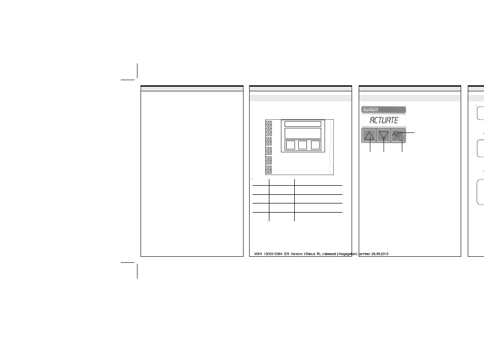
ELECTRICAL CONNECTION
BEDIENUNG
Display and keypad
Menu s
ARROW key
up
• Jump within a level
• Change parameters
ARROW key
up
• Jump within a level
• Change parameters
MANUAL/AUTOMATIC key
• Level 1: Change between manual and automatic mode
• Level 2: Confirm a parameter
(RETURN)
• Level 3: Select a menu item
(see also Menu Structure)
LED (yellow)
• Display of operating mode
• AUTOMATIC: LED flashes
• MANUAL: LED off
MANUAL/AUTOMATIC key
SETTIN
ARROW
key
up
ARROW
key
down
LED (yellow)
in the MANUAL/
AUTOMATIC key
Configuration of the terminals - Profibus PA
Use screened cable for connecting the bus and the binary
input in order to assure reliability and EC conformity. The
cable screens can be attached using the clamping screw (on
the post between the M20 bushings). The cable screens must
be attached at both ends. On the outside of the housing
there is a further screw for further connection to a suitable
earthing (grounding) point.
• To make electrical connections, open the cover of the
SIDE
Control by unscrewing the 2 screws.
Bus (+)
Bus (-)
Bus (+)
Bus (-)
81
82
n.c.
41 (+)
42 (-)
51 (+)
52 (-)
n.c.
Terminal Allocation
External connection
BUS (+)
PROFIBUS PA
(IN)
To IEC 1158-2 (either polarity
between input terminals)
BUS (-)
PROFIBUS PA
(IN)
BUS (+)
PROFIBUS PA
(OUT)
To IEC 1158-2 (either polarity
between output terminals)
BUS (-)
PROFIBUS PA
(OUT)
th
Contact addresses / Kontaktadressen
Germany / Deutschland / Allemange
Bürkert Fluid Control System
Sales Centre
Chr.-Bürkert-Str. 13-17
D-74653 Ingelfingen
Tel. + 49 (0) 7940 - 10 91 111
Fax + 49 (0) 7940 - 10 91 448
E-mail:
International
Contact addresses can be found on the internet at:
Die Kontaktadressen finden Sie im Internet unter:
Les adresses se trouvent sur internet sous :
www.burkert.com Bürkert / Company / Locations