Burkert Type 8635 User Manual
Page 3
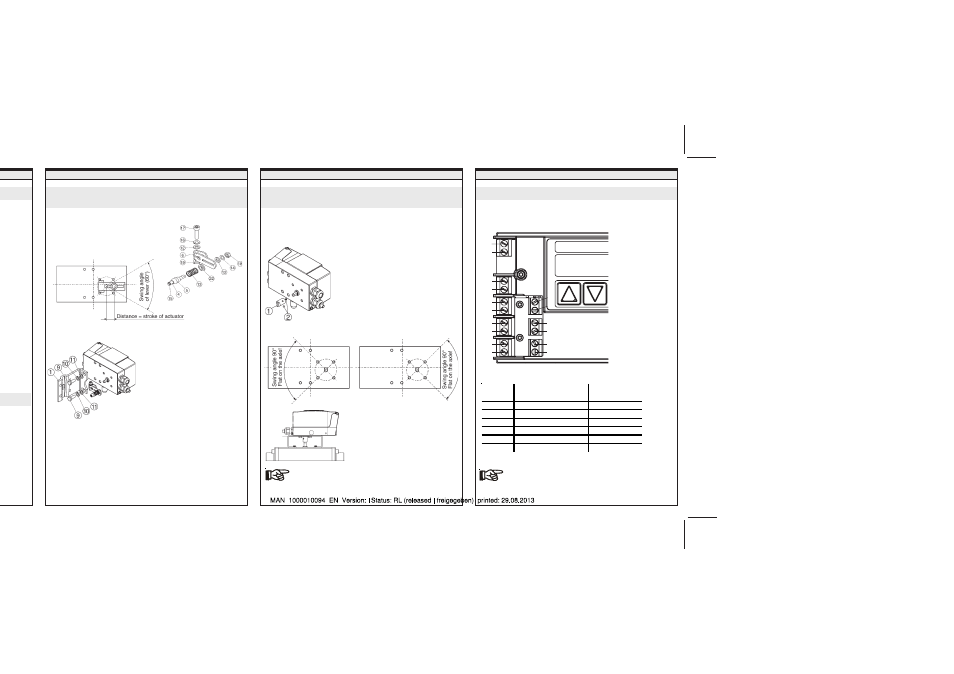
VALVE CONNECTION
Attachment to a continuous valve with linear
actuator acc. to NAMUR
d (NC):
(NO):
VALVE CONNECTION
Configuration of the terminals
ELECTRICAL CONNECTION
valves:
at piping
e the
mber of the
ctuator
• Assemble the lever (if not preassembled). The distance of
the driving pin from the axle should
be equal to the stroke. This results
in a swing angle of the lever of 60°.
The scale printed on the lever
is irrelevant.
• Fix the lever onto the axle of the SIDE
Control.
• Fix attachment bracket (1) to the SIDE
Control.
Alignment of the lever mechanism
The lever mechanism can be aligned properly only when the
device has been connected electrically and pneumatically.
• In the manual mode, move the actuator to half stroke
(corresponding to scale on actuator).
• Move the device vertically until the lever is horizontal.
• Fix the device finally to the actuator.
Attachment to a continuous valve with part-turn
actuator
• Select the M8 thread on the
SIDE
Control such that the
conical roller (5) on the lever of
the position sensor can move
freely in U-piece (2) on the
actuator over the entire stroke.
• Mount the U-piece on the drive
spindle of the actuator.
• Attach the SIDE
Control to the cast
frame or post yoke of the actuator
according to NAMUR procedure.
• To make electrical connection, open the cover of the
SIDE
Control by unscrewing the 2 screws.
Connection of a potential equalization conductor
(PE) to the electronics is not required.
If after starting the function
X.TUNE the message
X.ERR 5 appears in the LC display, the alignment of
the axle of the SIDE
Control to the axle of the
actuator is incorrect.
• Push adapter (1) onto the axle of the
SIDE
Control and fix it with 2
setscrews (2). One of the setscrews
should press onto the flat on the axle
(to prevent slip!). It must be assured
that the axle of the SIDE
Control can
move only in one of the ranges
shown below in the drawings.
Observe the flat on the axle!
• Determine the orientation of attachment of the SIDE
Control
(parallel to the actuator or rotated by 90°).
• Determine the basic position and direction of rotation of the
actuator.
• Place the SIDE
Control on the
bracket and fix it.
• Mount the SIDE
Control with the
bracket on the part-turn
actuator.
1st possibility:
2nd possibility:
Terminal
Allocation
External
connection
11 +
Setpoint +
4 ... 20 mA signal
12 -
Setpoint -
GND
13 +
Process value + (option) 4 ... 20 mA signal
14 -
Process value - (option)
GND
31
Actual value output +
32
Actual value output -
11
12
81
82
13
14
41
42
51
52
31
32
86
85
83
84