Burkert Type 8631 User Manual
Page 5
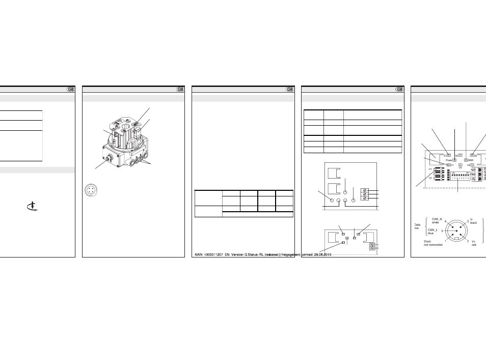
Data bit
configuration
D3
D2
D1
D0
Input
initiator 1
Input
initiator 2
Input
diagnosis
Output
valve 1
Parameter bit
configuration
P3
P2
P1
P0
not connected
Initiator 2
data bit D2
Bus connector
M 12
Intitiator 1
data bit D3
Valve 1
data bit D0
Control ports
connection 2
1
pressurized when
valve 1 = 1
IO code:
D hex (1 output, 3 inputs)
ID code:
F hex (ext. ID-Codes 1 and 2 = F)
Profile:
S - D. F. F
Certification:
yes, Cert.-no. 32901 (to V.2.11)
Watchdog function
yes
No. of valves /
power consumption
1 x 1 W
Power reduction
yes, after ca. 30 ms
Bus connection
- via M 12 plug
(Pin 1 = Bus +, Pin 3 = Bus -)
- via screw terminals and
PG bushing
Bus drive via AS interface
BUS COMMUNICATION
ators / proximity switches or limit switches:
ng of the TOP
Control ON/OFF and
ators using the setscrews (see illustration:
the control air).
ard
Turn anticlockwise:
movement downward
on commissioning
hanical limit switch
e actuation N
e actuation L 1
ply to limit switches
put common pole
put limit switch 2 (NC)
put limit switch 2 (NO)
put limit switch 1 (NC)
put limit switch1 (NO)
ply to limit switches
Status display
Programming data
sion
Standard Device
Pin 1: Bus +
Pin 3: Bus -
2
3
4
Device for A/B-Slave addressing
Observe bit configuration!
1
LED 1 Bus
(green)
LED 2 Bus
(red)
Status signalled
off
off
POWER OFF
off
on
no data traffic (watchdog expired
with slave address non-zero)
on
off
ok
flashes
on
slave adress = 0
off
flashes
Overload of sensor supply
Standard addressing
LED (yellow)
initiator 1
LED 2 Bus
(red)
LED (yellow)
initiator 2
LED 1 Bus
(yellow)
LED (green)
valve on
ASI +
ASI -
n. c.
A/B-Slave addressing
LED (yellow)
initiator 1
LED 2 Bus
(red)
LED (yellow)
valve on
LED 1 Bus
(green)
ASI +
ASI -
LED (yellow)
initiator 2
Plug connector
for Initiator S1
Plug
connector
for valve
LED for initiator 1
LED for
valve 1
MNS LED =
Module Network
Power LED
DIP switches for
address and data rate
L
Bus connection (circular plug connector M
L CONNECTION
BUS COMMUNICATION
BUS COMMUNICATION
BUS COMMUNICATION
Bus drive via AS interface
Bus drive via AS interface
IO code:
D hex (1 output, 3 inputs)
ID code:
A hex (ext. ID-Codes 1 = 7 hex and 2 = E hex)
Profile:
S - D. A. E
Certification:
yes, Cert.-no. 47601 (to V.2.11)
Bus drive via DeviceNet