Burkert Type 8630 User Manual
Page 2
ORMATION
TECHNICAL DATA
Technical data / possible extensions
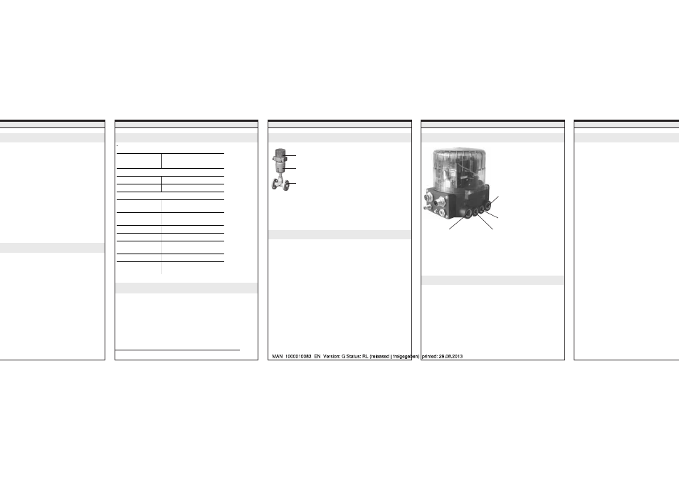
CONSTRUCTION AND FUNCTIONS
According to the operating conditions, different process valves
from the Bürkert programme can be combined with the
TOP
Control Continuous. Suitable alternatives are slanted and
straight seat control valves, diaphragm or ball valves.
Overview
FLUID CONNECTION
ELECTRICAL CONNECTION
Control air connection
Connections
Position controller
The position of the drive (stroke) is controlled
corresponding to the position set-point. The position set-
point can be predetermined by an external standard
signal.
Process controller (option)
The TOP
Control Continuous is combined in a control loop.
The stroke of the valve is calculated from the process set-
point and the process actual value via the control
parameters (PID controller). The process set-point can be
predetermined by an external signal.
Functions
Connector 1
Supply pressure
3 ... 7 bar
Connector 2.1: (mounted ex-works)
a) Action power-off closed (NC):
Actuator:
Bottom connector
b) Action power-off open (NO):
Actuator:
Top connector
Connector 3:
Exhaust air silencer
2 possibilities
• Multipole connection
• Heavy-gauge threaded union
Signal values
• Supply voltage:
24 V DC
• Set-point (process/position controller): 0 ... 20 m
0 ... 5 V; 0
• Actual value (process controller only): 4 ... 20 m
frequency
* Process actual value (option process controlle
Only the possibility of signal value 4…20 mA is repr
these instructions.
For connecting other kinds of signal: see
Operating
for TOP Control Continuous.
TOP
Control Continuous
Actuator
Valve
Connector 2.2:
For double-acting drives
ains electronic components which react
electrostatic discharge (ESD). Contact with
charged persons or objects will damage these
the worst case they are immediately destroyed
ommissioning.
requirements according to EN 100 015 – 1 in
e or eliminate the possibility of damage
pt electrostatic discharge. Take care also not
nic components when the supply voltage is
ATTENTION EXERCISE CAUTION WHEN
HANDLING!
ELECTROSTATICALLY ENDANGERED
COMPONENTS / ASSEMBLIES
Installing the valve
• Installation attitude optional; preferably as above.
• Take note of the flow direction; generally applicable for control
valves: Free-stream under seat!
• Make sure pipelines are free of all dirt and contamination!
• Make sure the pipelines are aligned before connecting the valve
housing.
• In the case of welded housings, be sure to remove the drive
before welding in the housing.
ended purpose
ly with the directions in these instructions, also the
ting conditions and permissible data according to
630, to ensure that the device functions correctly and
ble throughout its life. In the event of non-
hese instructions, also of impermissible
e device, we waive all liability and the guarantee for
accessory parts is cancelled! The device is
ely for use as a positioning and process control
rent use or use going beyond this is considered
ürkert is not liable for damage resulting from such
arried solely by the user.
• Analogue position check-back signal
• Inductive proximity switch
• Binary input / output
• Bus communication
• Software additional functions
Possible extensions
We reserve the right to make technical changes without notice.
tions
Operating conditions
Ambient temperature 0 ... +50°C
Degree of protection
IP 65 according to EN 60529
Electrical data
Voltage supply
24 V DC ± 10 %
Safety class
3 according to VDE 0580
Pneumatic data
Control medium
Quality classes
to DIN ISO 8573-1
- Dust content
max. particle size 40 µm
max. particle density 10 mg/m
3
- Water content
max. pressure dew point -20°C
- Oil content
max. 25mg/m
3
Temperature range
of compressed air
-10 ... +50°C
Pressure range
3 ... 7 bar
Fluctuation of supply
pressure
max. ± 10 % during operation
The fixing screw (connec-
tion between Top
Control
and process valve) may only
be tightened with a
maximum torque of 1.2 Nm.