Electrical data, Installation – Burkert Type 6114 User Manual
Page 4
english
12
ELECTRICAL DATA
Ensure that the polarity is correct, otherwise
the device will not function!
Observe color coding of the cable: (black / red)
Operating voltage
According to type label
Standard version ± 10 %
Clocked version + 10 %
Nominal power
1.1 W
Nominal operating mode Continuous operation, ED 100 %
Actuation of bistable version:
Polarity
Identification
Pulse duration min. 20 ms
(black)
(red)
+
Valve (P seat) is
closed
Valve (R seat) is
open
–
Valve (P seat) is
open
Valve (R seat) is
closed
english
13
INSTALLATION
Safety Instructions
WARNING!
Risk of injury from improper assembly!
• Installation may be carried out by authorised technicians
only and with the appropriate tools!
Risk of injury from unintentional activation of the
system and an uncontrolled restart!
• Secure system from unintentional activation.
• Following assembly, ensure a controlled restart.
Fluid Installation
WARNING!
Risk of injury from high pressure!
• Before loosening the lines and valves, turn off the pressure
and vent the lines!
Important operating condition for the preven-
tion of malfunctions: The valve must have a mini-
mum distance of 5 mm from other ferromagnetic
materials.
english
14
Installation location: any, drive preferably upwards.
Prior to the installation:
→
Clean any dirt off the pipelines and flange connections.
→
To prevent malfunctions, install a filter (5 µm) in front of
the valve.
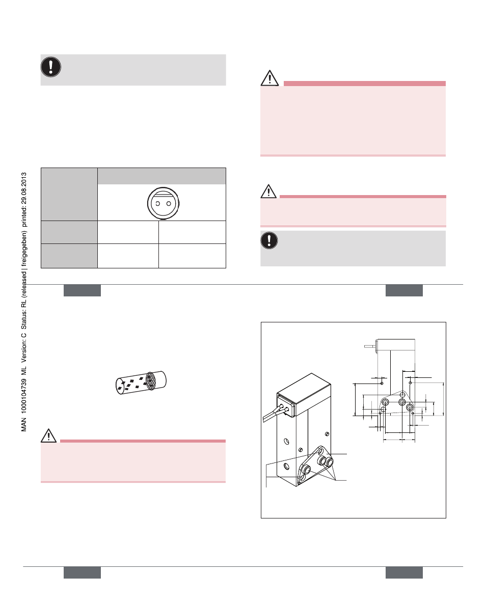
Assembly of Type 6114:
(See diagram: Assembly drawing)
WARNING!
Danger - escaping medium!
Leaking connections if seal seated incorrectly.
• Ensure that the supplied sealing gasket is seated
correctly.
→
Insert the sealing gasket into the valve.
→
Correctly allocate the fluid connection configuration 1,
2 and 3 to the valve and the connection plate.
→
Drill holes according to the drill hole-pattern.
→
Screw valve onto the connection plate
→
Check valve for leakage.
english
15
Valve with fastening elements
Fluid connections
(see "Pneumatic data")
2,25
2
15,6
6
6,2
3,7
8,1
1,1
9,1
1,1
7
3
2,5
6,5
15,
85
1
1
Bore hole
illustration:
Bores for fastening
screws
Ø 2 mm
Sealing gasket
Figure: Assembly drawing
Type 6114