Brooks, Model 5851e, Caution – Brooks Instrument 5851E User Manual
Page 39
Brooks
®
Model 5851E
4-7
Section 4 Maintenance
Installation and Operation Manual
X-TMF-5851E-MFC-eng
Part Number: 541B104AAG
November, 2008
Note: It is recommended that all O-rings be replaced during controller
assembly. All O-rings should be lightly lubricated with Halocarbon lubricant
(part of O-ring kit, Section 5) prior to their installation.
1. Examine all parts for signs of wear or damage, replace as necessary.
2. Place the restrictor O-ring on the restrictor assembly. Screw the
restrictor assembly (21) into the inlet side of the flow controller body
using the restrictor took, tighten hand tight.
The following steps must be performed as written. Placing the O-
rings on the sensor before it is installed will result in damage to
the O-rings causing a leak.
CAUTION
3. Place the end block O-ring in position and install the end block with the
4 hex socket screws. Tighten these screws to 49 inch-lbs. Do not over
tighten.
The end block screws (31) and the valve screws (3) are not
interchangeable. The end block screws are stronger and are needed
for the pressure rating. The end block screws are darker in color
and can be attracted by a magnet.
CAUTION
4. Press the lubricated sensor O-rings (17) into the flow controller body
(14). Install the sensor assembly and secure with two screws (18) and
washers (19) tightened to 15 in/lbs.
5. Install the orifice (12) and its O-ring (13), using a 3/8 nut driver. Insure
that the orifice is fully seated but do not overtighten.
6. Insert the valve preload spacers (10), if used, into the valve cavity in the
flow controller body (14). Use care to preserve the correct order.
7. Install the valve plunger assembly (7, 8, 9 and 11) on the preload
spacers (10). Install air gap spacers (10), if used, on top of the valve
springs.
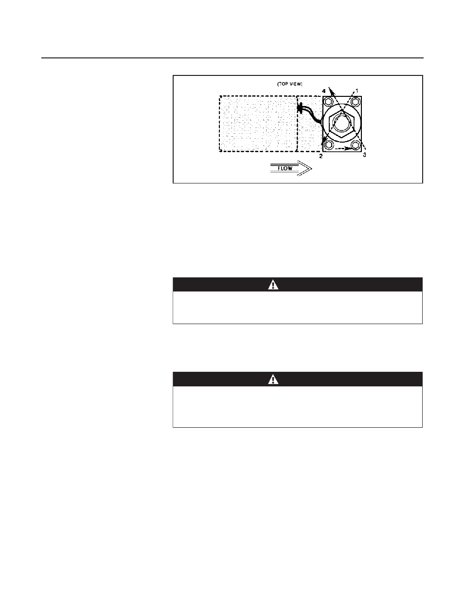
8. Install the valve stem assembly (6), secure with the valve retaining plate
(4) and four hex socket screws (3). When installing the screws they
should first make light contact with the plate, which should be checked
to insure that it makes full contact around the stem assembly. Torque
the screws securing the valve retaining plate in a diagonal pattern
(Refer to Figure 4-1) to 15 in/lbs.
Figure 4-1 Torque Sequence for the Valve Retainer Plate