Brooks, Model 5851e – Brooks Instrument 5851E User Manual
Page 23
3-3
Brooks
®
Model 5851E
Section 3 Operation
Installation and Operation Manual
X-TMF-5851E-MFC-eng
Part Number: 541B104AAG
November, 2008
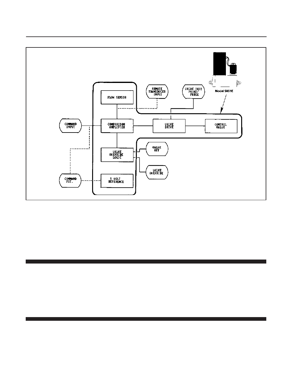
Figure 3-2 Flow Control System Block Diagram
• Remote Transducer Input
Accessed via Terminal 5 on the Card Edge or Pin 15 on the D-Connector
version. This feature allows the use of the integral control electronics and
valve with the signal from an external 0-5 Vdc signal. The mass flow signal
from the Model 5851E is still available for process monitoring. This function
is jumper selectable. Refer to Section 2-9.
3-2 Operating Procedure
a. Apply power to the controller and allow approximately 45 minutes for
the instrument to warm-up and stabilize its temperature.
b. Turn on the gas supply.
c. Command 0% flow and observe the controllers output signal. If the
output is not 0 mVdc (±10 mVdc), check for leaks and if none are found
refer to the zero adjustment procedure in Section 3-3.
d. Set the command for the desired flow rate to assume normal operation.
3-3 Zero Adjustment
Each Model 5851E is factory adjusted to provide a 0 ±10 mVdc signal at
zero flow. The adjustment is made in our calibration laboratory which is
temperature controlled to 21.1°C (70°F ±2°F). After initial installation and
warm-up in the gas system the zero flow indication may be other than the
factory setting. This is primarily caused by changes in temperature
between our calibration laboratory and the final installation. The zero flow
reading can also be affected to a small degree by changes in line pressure
and mounting attitude.