Brooks, Model 5851e – Brooks Instrument 5851E User Manual
Page 14
2-4
Brooks
®
Model 5851E
Section 2 Installation
Installation and Operation Manual
X-TMF-5851E-MFC-eng
Part Number: 541B104AAG
November, 2008
2-6 In-Line Filter
It is recommended that an in-line filter be installed upstream from the
controller to prevent the possibility of any foreign material entering the flow
sensor or control valve. The filtering element should be periodically
replaced or ultrasonically cleaned.
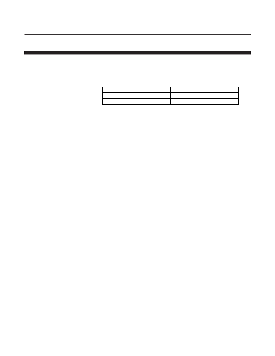
Note: The above table lists the maximum recommended porosity for each
flow range. It is recommended that the minimum micron porosity that does
not limit the full scale flowrate be used.
Electrical Interfacing
To ensure proper operation the Model 5851E must be connected per
Figures 2-3 and 2-4, and configured according to Sections 2-6 and 2-12.
At a minimum the following connections must be made for new
installations.
Chassis Ground
0-5 Volt Signal Common
0-5 Volt Signal Output
+15 Vdc Supply
-15 Vdc Supply
Command Input
Command Common
Supply Voltage Common
For installations which replace Unit Instruments UFC-1000's, (Card
Edge version) Pin 10 is frequently grounded. In these situations the 5 Volt
reference output must be disabled. Refer to Section 2-12.
For installations which will be connected to Brooks secondary electronics,
the Card Edge version must have the 5 Volt reference enabled on Pin 10.
Refer to Section 2-12. If the Model 5851E was shipped as a system with
Brooks secondary electronics then the electronics will already be
configured properly.
Note: To obtain access to the jumpers for the following options the
electronics cover can must be removed. Remove the can by removing the
three screws and the valve connector. The can must be replaced before
returning the unit to service.
Maximum Flow Rate
Recommended Filter Size
10 to 30 slpm
15 Micron
Above 30 slpm
30 Micron
Table 2-1 Recommended Filter Size