Brooks, Model 5851e – Brooks Instrument 5851E User Manual
Page 17
2-7
Brooks
®
Model 5851E
Section 2 Installation
Installation and Operation Manual
X-TMF-5851E-MFC-eng
Part Number: 541B104AAG
November, 2008
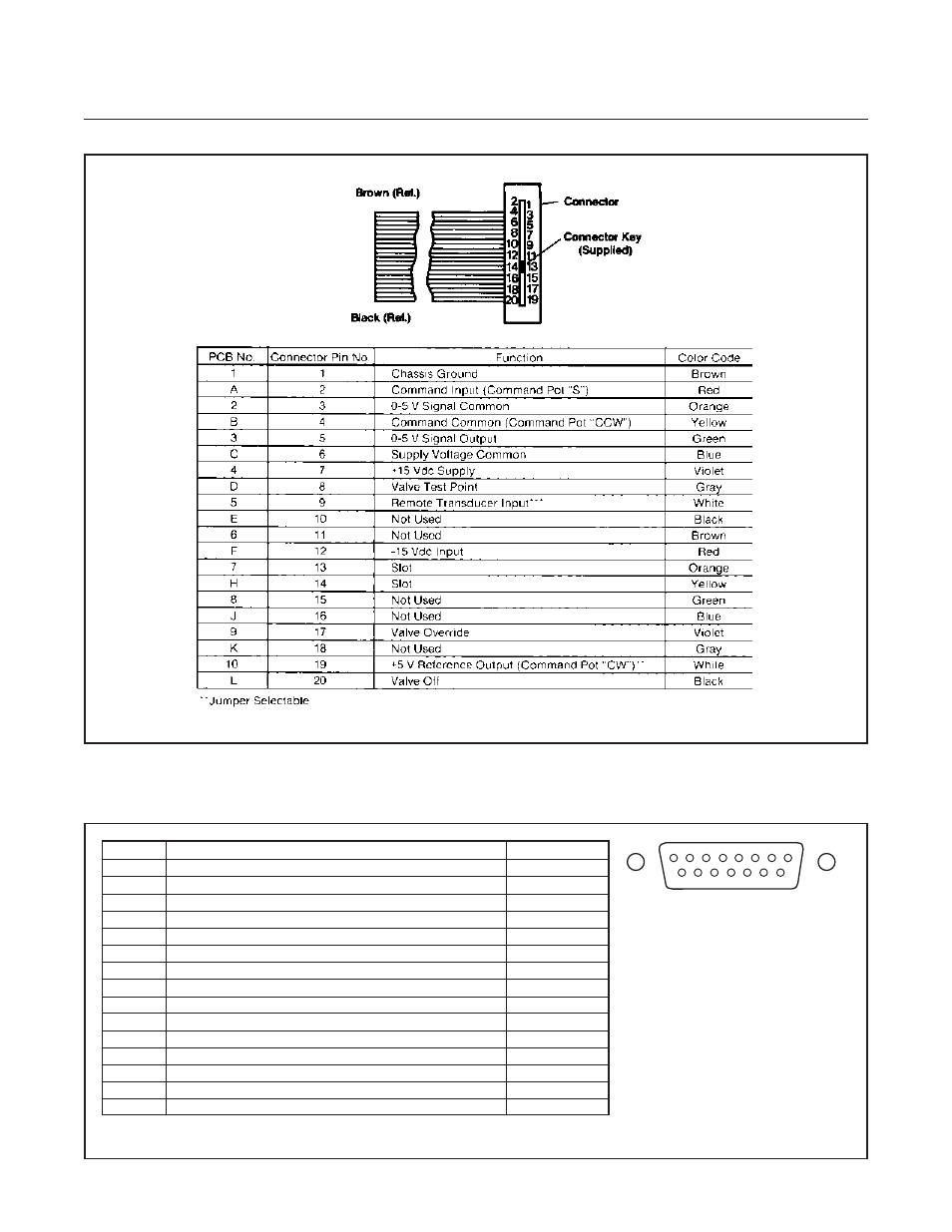
Figure 2-3 Model 5851E Card Edge Connector Hookup Diagram
Figure 2-4. D-Connector Pin Arrangement.
PIN NO.
FUNCTION
COLOR CODE
1
Cmd. Common (Command Pot "CCW")
Black
2
0-5 Volt Signal Output
White
3
N/C
Red
4
Valve Off
Green
5
+15 Vdc Supply
Orange
6
-15 Vdc Supply
Blue
7
Valve Test Point
Wht/Blk
8
Cmd. Input or Cmd. Pot "S"
Red/Blk
9
Supply Voltage Common
Grn/Blk
10
0-5 Volt Signal Common
Org/Blk
11
+5 Volt Reference Output (Command Pot "CW")
Blu/Blk
12
Valve Override
Blk/Wht
13
Not Used
Red/Wht
14
Chassis Ground
Grn/Wht
15
Remote Transducer Input*
Blu/Wht
*Jumper Selectable
Notes:
1. Cable shield tied to chassis ground
in meter connector. Make no
connection on customer end.
2. All power leads must be connected
to power supply.
1
15
9
8
- QMBC (52 pages)
- SolidSense II (28 pages)
- SLA7810/20 (36 pages)
- SLA5810/20 (50 pages)
- SLA5840 (46 pages)
- SLA7840 (40 pages)
- 5866E (65 pages)
- IPS122 2 Indicating Pressure Switches" (18 pages)
- IPT122 2 Indicating Pressure Transmitters" (22 pages)
- 8601 (20 pages)
- PTI Metal Seal Mass Flow Controller w/Real-Time Flow Error Detection & Advanced Diagnostics (82 pages)
- SLA5800 Series (76 pages)
- 5800S Series (50 pages)
- 4800 Series (50 pages)
- 5850EM (74 pages)
- 5851EM (62 pages)
- 5850E (64 pages)
- 5860E (46 pages)
- 5861E (44 pages)
- 5850i (62 pages)
- 5851i (62 pages)
- 5860i (48 pages)
- 5861i (48 pages)
- 5881/91 (40 pages)
- GF40 (78 pages)
- SLAMf Series (76 pages)
- Mfi Series (82 pages)
- 0254 (124 pages)
- 0260 (14 pages)
- CMC Series (36 pages)
- XacTorr CMX45 (64 pages)
- MT3809G (78 pages)
- MT3809E (72 pages)
- MT3810 (66 pages)
- 3600 Series (56 pages)
- 3750 (64 pages)
- Control Valve (16 pages)
- GT1000 (52 pages)
- 1100 Series (52 pages)
- 1307 (18 pages)
- 1358 (44 pages)
- 1350 (46 pages)
- 1250 (2 pages)
- FC8800 Series (48 pages)