Brooks, Model 5851e – Brooks Instrument 5851E User Manual
Page 28
3-8
Brooks
®
Model 5851E
Section 3 Operation
Installation and Operation Manual
X-TMF-5851E-MFC-eng
Part Number: 541B104AAG
November, 2008
Adjust the span potentiometer until the voltage at TP1 is equal to the value
calculated above. Recheck the flow rate after the flow is stable (at least
2 minutes). Repeat this check and adjustment procedure until the
measured flow rate is within 1% of the desired flow rate.
Note: The voltage at TPl is -100 times the output voltage of the sensor.
This voltage can range from -1.2 to -12 Volts, however it is recom-
mended that this voltage stays between -2.0 and -9.0 Volts for proper
operation. If the recommended voltage range exceeds the desired
accuracy signal stability may not be achieved. If one of the limits is
reached check the orifice and restrictor sizing procedures. Refer to
Sections 4-6 and 4-7 respectively.
g. Set the command potentiometer for 0% of flow. Connect the DVM
positive lead to flow signal output (Terminal 3 Card Edge, Pin 2
D-Connector) and the negative lead to TP4. Readjust the zero potenti-
ometer for an output of 0 mV ±2 mV as necessary.
h. Set the command potentiometer for 50% of flow (2.500 V) and measure
the flow rate. Calculate the error as a percentage of full scale.
Measured
-
Desired Flow
Flow Rate
Rate
Full Scale Error = 100% x
Full Scale Flow Rate
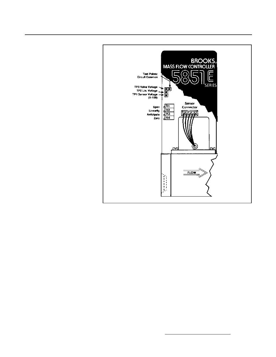
Figure 3-6 Adjustment Potentiometer Location
TP4