Solidsense ii, Series – Brooks Instrument SolidSense II User Manual
Page 25
Installation and Operation Manual
X-PR-SolidSense II-PT-eng
Part Number 541B160AAG
July, 2011
SolidSense II
®
Series
2-9
Section 2 Installation
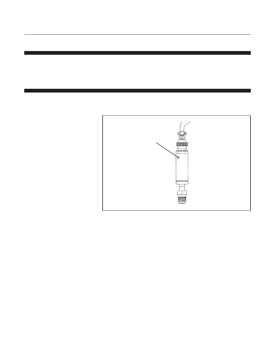
Position the SolidSense II pressure transducer with the electrical connector
facing pointing upward. Using a small, flat-bladed screw driver, turn zero
adjustment screw in a clockwise direction to increase the signal. Turn the
screw in a counterclockwise direction to decrease the signal.
Figure 2-9 Zero Adjustment Screw Location on the (Standard
SolidSense II pressure tranducers)
Zero Adjustment Screw
2-10 Zero Adjustment
The SolidSense II pressure transducer is factory calibrated and does not
normally need a field adjustment. If a field adjustment becomes necessary,
adjust the zero as noted below.
2-10-1 Zero Adjustment (SolidSense II Standard Pressure Transducers)
On standard SolidSense II pressure transducer models, the zero
adjustment screw is located on the body as shown in Figure 2-8.
- QMBC (52 pages)
- SLA7810/20 (36 pages)
- SLA5810/20 (50 pages)
- SLA5840 (46 pages)
- SLA7840 (40 pages)
- 5866E (65 pages)
- IPS122 2 Indicating Pressure Switches" (18 pages)
- IPT122 2 Indicating Pressure Transmitters" (22 pages)
- 8601 (20 pages)
- PTI Metal Seal Mass Flow Controller w/Real-Time Flow Error Detection & Advanced Diagnostics (82 pages)
- SLA5800 Series (76 pages)
- 5800S Series (50 pages)
- 4800 Series (50 pages)
- 5850EM (74 pages)
- 5851EM (62 pages)
- 5850E (64 pages)
- 5851E (64 pages)
- 5860E (46 pages)
- 5861E (44 pages)
- 5850i (62 pages)
- 5851i (62 pages)
- 5860i (48 pages)
- 5861i (48 pages)
- 5881/91 (40 pages)
- GF40 (78 pages)
- SLAMf Series (76 pages)
- Mfi Series (82 pages)
- 0254 (124 pages)
- 0260 (14 pages)
- CMC Series (36 pages)
- XacTorr CMX45 (64 pages)
- MT3809G (78 pages)
- MT3809E (72 pages)
- MT3810 (66 pages)
- 3600 Series (56 pages)
- 3750 (64 pages)
- Control Valve (16 pages)
- GT1000 (52 pages)
- 1100 Series (52 pages)
- 1307 (18 pages)
- 1358 (44 pages)
- 1350 (46 pages)
- 1250 (2 pages)
- FC8800 Series (48 pages)