Communication Concepts FM-1KW Broadcast Application Note User Manual
Page 8
8
RF Reference Design Data
Freescale Semiconductor
MRFE6VP61K25H MRFE6VP61K25HS FM Broadcast
Reliability
Mean time to failure (MTTF) is defined as a 10% reduction
in current handling capability on 50% of the devices within a
given sample size. The primary factor in device failure is due
to metal electromigration on the die surface. Once the
average operating conditions for a given application are
determined, then the MTTF can be calculated using the
thermal resistance R
th
value given in the MRFE6VP61K25H
product data sheet.
Example: If the desired operating output power is 1100 W,
with 80% drain efficiency.
• I
Drain
= 1100 W / (80% × 50 V) ~ 27.5 A
• MRFE6VP61K25H R
th
= 0.15°C/W, case temperature =
80°C
• Dissipated power = P
dc
-- P
out
+ P
in
• Dissipated power = 50 V × 27.5 A -- 1100 W + 4 W = 279 W
• Temperature rise = 279 W × 0.15°C/W = 42°C
• T
J
= T
rise
+ T
C
= 42°C + 80°C = 122°C
Utilizing Figure 12 which calculates MTTF versus I
Drain
and T
J
; I
Drain
= 27.5 A, MTTF for this example is 2700 years.
250
100000
90
T
J
, JUNCTION TEMPERATURE (°C)
Figure 12. MTTF versus Junction Temperature
1000
100
1
110
130
150
170
190
MTTF
(YEAR
S)
210
230
10000
10
24 Amp
32 Amp
28 Amp
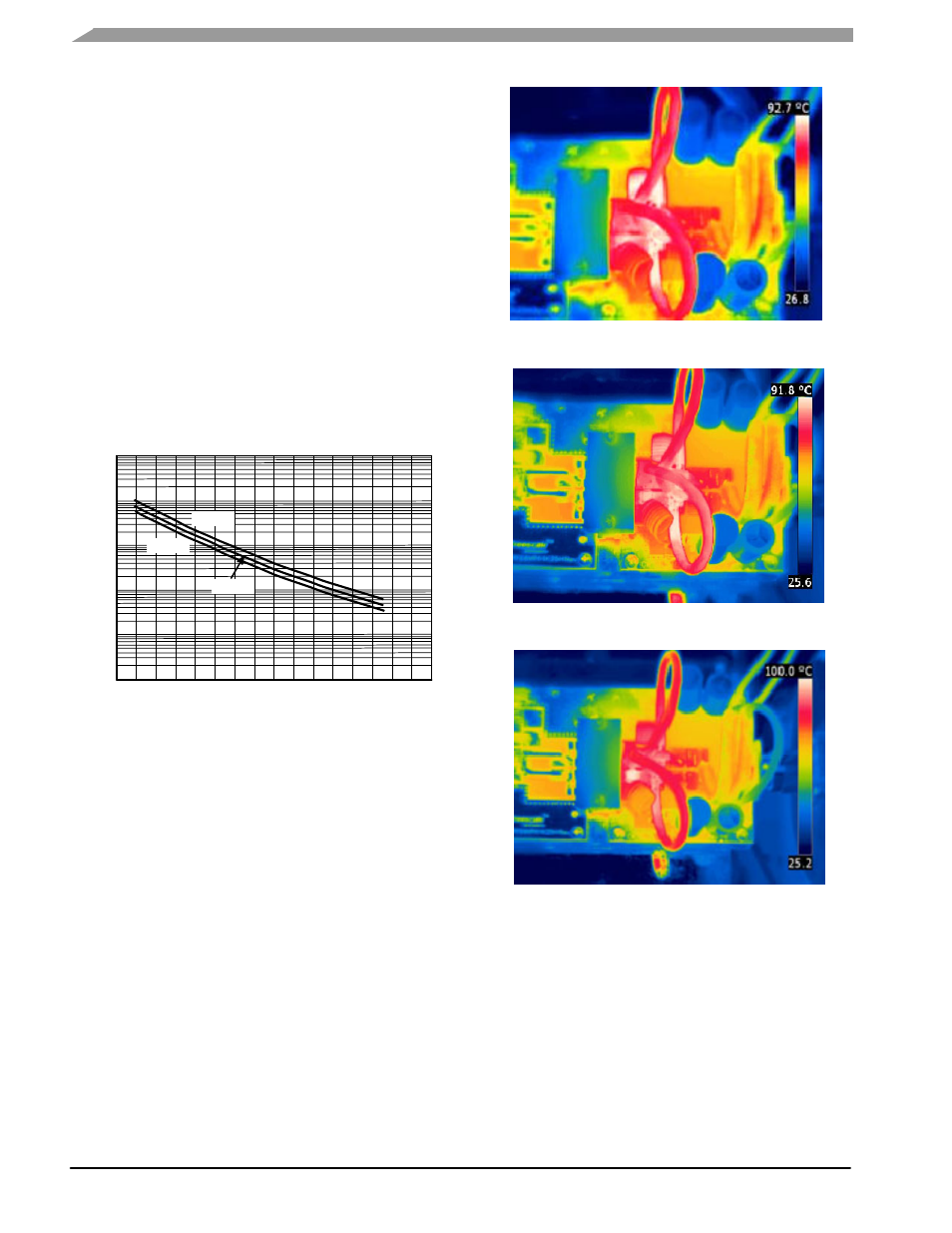
THERMAL MEASUREMENTS
Thermal images of the MRFE6VP61K25H FM broadcast
reference circuit were taken using a FLIR Infrared(IR) T360
camera. The hottest point observed was located at the
Coax1 and Coax2 junction point with the C4 mica capacitor
at 108 MHz. The recorded temperature was 100°C after
10 minutes of operation to reach steady state temperature.
Due to the high efficiency achieved by the FM broadcast
reference fixture, the overall baseplate temperature remains
relatively cool at around 60°C, with forced air cooling at
25°C.
87.5 MHz, 1100 W CW, 79% Drain Efficiency
Figure 13. IR Images of the Output Matching Network
98 MHz, 1100 W CW, 78% Drain Efficiency
108 MHz, 1100 W CW, 80% Drain Efficiency