Automatic timer flush package option – ClimaCool IOM FLEX SERIES User Manual
Page 20
www.climacoolcorp.com
www.climacoolcorp.com
®
18
reservoir. The power supply and timer controls for the valve
package are housed inside the ATF control box. The ATF
controls can be pre-programmed to set the flushing duration
and the time interval between flushes.
System Components:
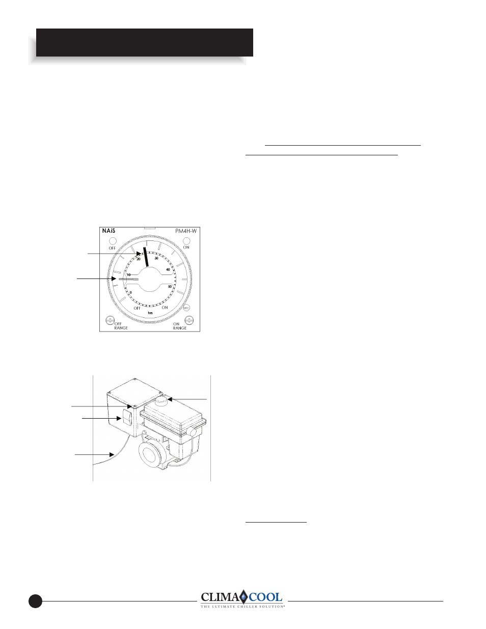
A. Timer Based Valve Controller (see Fig. 1) sets the flush
duration (length of the flush) and the flush interval (time
between flushes).
B. Electric Ball Valve: designed for dirty water use (see Fig.
1 & 2).
Fig. 1
A
GREEN POINTER
INNER RING
(LENGTH OF FLUSH)
(FACTORY SET AT
8-SECONDS)
RED POINTER
OUTER RING
(TIME BETWEEN
FLUSHES)
(FACTORY SET AT
24-HOURS)
Fig. 2
B
[email protected] POWER
FROM PDA OR 120V PLUG
IN TRANSFORMER
OPEN/CLOSE
INDICATOR
COVER-PLATE SCREWS
(4) IN CORNERS OF BOX
(TIMER BASED VALVE
CONTROLLER)
CONTROL SWITCH
Operation Instructions:
Flush valve line must be piped to atmospheric pressure such
as an open floor drain. The flush line should not undergo
Automatic Timer Flush Package Option
any changes in elevation and should be sloped downward in
the direction of drainage. DO NOT PIPE THE FLUSH OR
DRAIN LINE INTO A PRESSURIZED LINE.
Note: The Automatic Timer Flush Package needs to be
programmed when it is received by the end-user. The
programming is simple and takes only a few moments.
However, because every application has different parameters
that affect the required frequency between flushes and the
duration of the flush, the end-user must choose the controller's
settings (refer to your specific strainer manual).
To program the ATF Controller:
Plug the transformer into a 120-VAC outlet.
Insert the 12-VDC plug coming from the transformer into the
jack on the underside of the ATF box.
Test for power by pressing the manual flush side of the
control switch (lower switch light should come on and the
valve will start to open).
Adjust the "ON-TIME" (Valve Open) by turning the inner
timer ring with the GREEN POINTER clockwise to increase
duration. ("ON-TIME" RANGE, See Fig. 1)
Adjust the "OFF-TIME" (Valve Close) by turning the outer
ring with the RED POINTER clockwise to increase duration.
("OFF-TIME" RANGE, See Fig. 1)
Set the control switch to auto flush. The red off light on the
timer will come on and the upper light on the switch will
come on and stay on. During the flush cycle the on light on
the timer and the lower switch light will come on.
Control Switch: (see illustration)
Control switch flushing is initiated by pressing and holding
down the manual control switch located on the front of the
controller. The manual flush control switch can also be used
to conveniently drain the water out of the strainer before
removing the conical screen element from the strainer
housing. A yellow indicator arrow on top of the ATF Valve
will rotate in sync with the ball valve to show the valve
position (open or closed). When the manual flush control
switch is released, the valve will automatically close.
SAFETY FIRST!
Keep fingers away from valve opening to avoid getting caught
in the moving parts. The electric motor supplies a sufficient
amount of power to cause personal injury. Take precaution