Climacool water piping configurations, The climacool, Modular chiller – ClimaCool IOM FLEX SERIES User Manual
Page 12
www.climacoolcorp.com
www.climacoolcorp.com
®
10
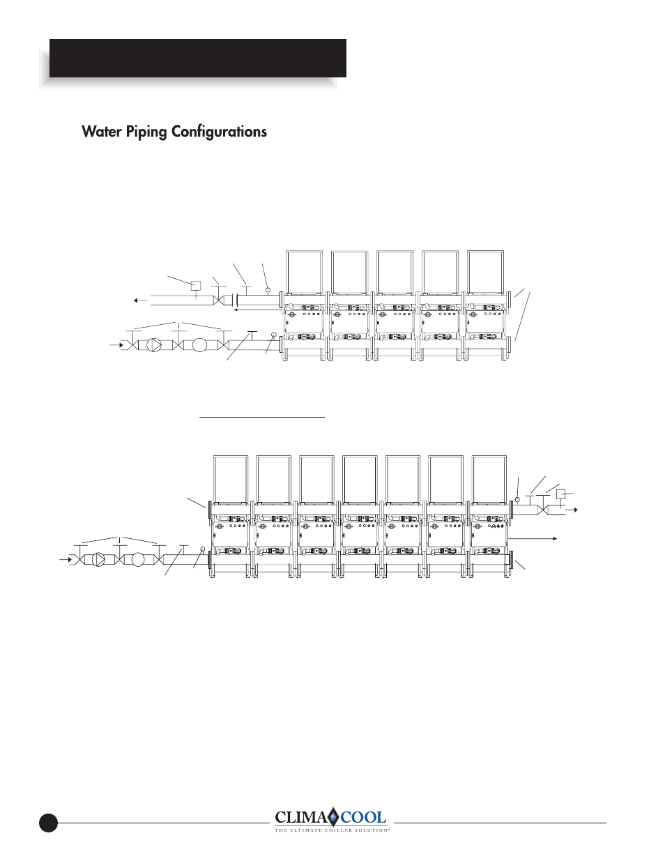
ClimaCool Water Piping Configurations
The ClimaCool
®
Modular Chiller -
Field Piping Direct Return - 1 to 5 Modules (Figure 1)
Unit 1
Unit 2
Unit 3
Unit 5
Unit 4
Blank Off
Plates
60” Sensor Location
(Field-Installed)
PressureTaps
with Shutoff Valves
& Gauges
Flow Out
Flow Switch
Isolation Valve
Thermometer Well
Thermometer Well
PressureTap
w/Shutoff
Valve &
Gauge
Isolation Valves
Strainer
Pump
Flow In
Blank Off
Plate
Blank Off
Plate
60” Sensor Location
(Field-Installed)
Unit 1
Unit 2
Unit 3
Unit 7
Unit 6
Unit 5
Unit 4
Thermometer Well
PressureTap
w/Shutoff
Valve &
Gauge
Isolation Valves
Strainer
Pump
Flow In
Flow Out
Thermometer Well
Flow Switch
Isolation Valves
Pressure Taps
with Shutoff Valves
& Gauges
NOTES:
1. Figures 1 and 2 are required piping for proper water regulation and distribution through ClimaCool
®
modular chillers.
2. Module order and incoming/outgoing water fl ow as shown in both Figure 1 and 2 can be set up as either a left-to-right or
right-to-left confi guration.
3. Condenser Hydronic Circuit shown. Piping confi gurations are similar for the chilled water hydronic circuit.
4. For condenser and chilled water (evaporator) inlet/outlet location dimensions, refer to Module Dimensional Data.
5. A fl ow switch (supplied by others) is a required safety device for ClimaCool
®
modular chillers on the chilled and condenser
water circuits.
6. Maximum water fl ow rates for both evaporator and condenser water header systems in one bank of modules is 1000 GPM.
Field Piping Reverse Return - (Preferred 1 to 5 modules) Required for 6 to 7 Modules (Figure 2)
7. The chilled water piping on each module is pre-insulated at the factory with ¾” closed cell foam rubber. Insulation (3/4”)
on the chilled water header connection flanges is to be applied in the field by the installer, after the modules are bolted
together on site.