Water piping configurations – ClimaCool UCW_H 30, 50, 70, 85 User Manual
Page 14
www.climacoolcorp.com
12
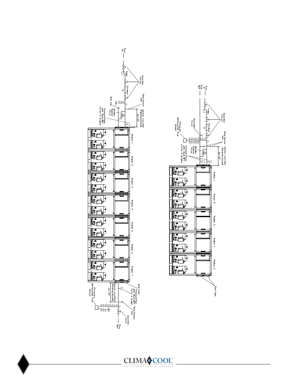
Water Piping Configurations
N
otes:
1 .
Figures 9 an
d 10 are required pipin
g for proper water regulation
an
d distribution
th
roug
h ClimaCool modular ch
illers
.
2.
M
odule order an
d in
comin
g/outgo
in
g water flo
w as sh
own
in both
Figure 9 an
d 10 can
be set up as eith
er a left-to-rig
ht or rig
ht-to-left con
fig
uration
.
3.
Con
den
ser h
ydron
ic circuit sh
own
. Pipin
g con
fig
uration
s are similar for th
e ch
illed water h
ydron
ic circuit.
4 .
Fo
r con
den
ser/h
eatin
g an
d ch
illed water (evaporator) inlet/outlet location
dimen
sion
s, refer to page 6 - Dimen
sion
Data
.
5.
A pressure differen
tial flow sen
sor is a required safety device for ClimaCool modular ch
illers on
th
e ch
illed an
d con
den
ser/h
eatin
g water circuits.
6 .
A strain
er with
a min
imum of 60 mesh
stain
less steel screen
is a required safety to
protect th
e brazed plate h
eat exch
an
gers on
both
ch
illed an
d con
den
ser/h
eatin
g water sides of th
e system
.
7.
M
aximum water flow rates for both
evaporator an
d con
den
ser/h
eatin
g water h
eader systems fo
r 30, 50 an
d 70 ton
modules in
on
e ban
k is 1,000 g
pm.
8.
M
aximum water flow rates for both
evaporator an
d con
den
ser/h
eatin
g water h
eader systems fo
r 85 ton
modules in
on
e ban
k is 2,400 gpm.
9 . Bypass is
mandatory
fo
r systems utilizin
g motoriz
ed valves
.
10
. Header bypass valve may be in
stalled at eith
er en
d of ban
k .
11
. For over seven
(7) modules, please co
nsult th
e fact
ory
.
Figure 9 - Field Piping Direct Return
Figure 10 - Field Piping Reverse Return