ClimaCool UCW_H 30, 50, 70, 85 User Manual
Page 13
11
www.climacoolcorp.com
ClimaCool offers two types of water header bypass kits, direct
return (Figure 6) and reverse return (Figure 7) as shown on
page 10 . The bypass kits must be installed on each water source
loop and controls are integrated with the CoolLogic software .
Installation location can be found on page 12 – Water Piping
Configuration.
This bypass can also be created with field supplied piping. The
design piping must accommodate one module’s worth of design
flow, and be positioned so that the temperature and differential
flow sensors sense active flow in the bypass mode. See Figures
9 and 10 on page 12 - Water Piping Configuration. The field
supplied piped chiller/heater system bypass must be controlled
by others. There are system communication delays, polling and
network conflicts that strictly prohibit the use of ClimaCool
sensors and controls for control of field supplied bypasses or
other field supplied items. Recommended method is to control
via differential pressure or gpm flow meters across the chilled
water/evaporator, hot water/condenser water systems .
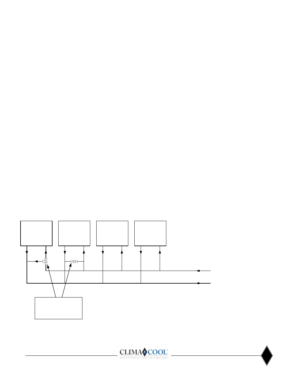
LOAD 1
FROM CHILLER BANK
TYPICAL LOAD BYPASS VALVE ARRANGEMENT
TO CHILLER BANK
LOAD 2
LOAD 3
LOAD X
TYPICAL CHILLED AND HOT WATER
LOAD SIDE BYPASS VALVES
SIZE EQUIVALENT TO ONE MODULE
WORTH OF FLOW
Figure 8 - Typical Load Bypass Valve Arrangement
Load Side System Bypass (Air Handlers, Fan
Coils, etc.)
A load system bypass is required for preventing pump
deadheading, allowing active flow system sensing and
preventing starving flow from the chiller/heater system.
Examples of an acceptable load side system bypass are:
•Utilize a quantity of 3-way control valves on the largest
loads farthest from the chiller/heater system .
•Field piping with a control valve to provide a bypass across
the larger system loads when their 2-way valves go closed .
Please refer to Figure 8 for a typical load bypass
valve arrangement . The load side system bypass should be
sized for an absolute minimum of one module’s worth of
design flow. (Please refer to selection submittals for design
flow rates). A minimum of (6) six gallons per nominal system
ton are also required to maintain proper system thermal
inertia . This is to avoid short cycling of compressors in the
chiller/heater system as well as prevent nuisance alarms .