CEMB USA C71_2 evo (D) User Manual
Page 4
I 0637 -
4
2
2a
3
A
B
GB
3 - STARTUP
3.1 - Anchoring
The machine can operate on any fl at non resilient fl oor.
Make sure that the machine rests solely on the three support points provided (Fig.2a).
It is advisable to secure the system to the ground using the specifi c feet (Fig. 2a) if the machine is
continually used with wheels weighing over 35 kg.
3.2 - Electrical connection
The machine is supplied with a single-phase mains cable plus earth (ground).
(any extension cables must have a cross-section of no less than 2.5 mm
2
).
The power supply voltage (and mains frequency) is indicated on the machine identifi cation plate and cannot be
changed. Connection to the mains must always be made by expert personnel.
The machine must not be set up without proper earthing.
Connection to the mains should be through a slow acting safety switch rated at 16 A (230V) or 40A (115V). See
enclosed diagrams.
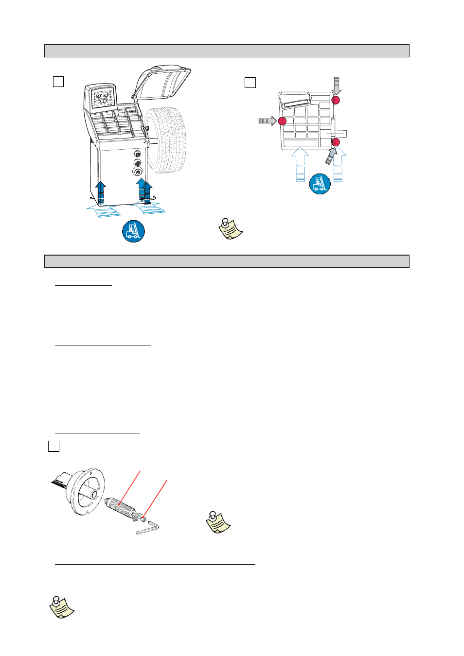
3.3 - Adapter mounting
►
►
►
2 - HANDLING AND LIFTING
The wheel balancer is supplied complete with cone adapters
for fi xing wheels with a central hole. Other optional adapters can be
mounted:
a) Remove the threaded end-piece A after unscrewing the screw B.
b) Mount the new fl ange (see attached sheets).
NOTE: CAREFULLY CLEAN THE COUPLING SURFACES
BEFORE PERFORMING ANY OPERATION.
3.4 - Wheel guard assembly and adjustment (optional)
a)
Fasten the components to the base as illustrated in specifi c exploded view.
b) With the guard closed check that the microswitch prod has slipped into place of the protection tube.
NOTE: DO NOT LEAN ON THE GUARD DURING THE WHEEL BALANCING CYCLE.
►
NOTE: DO NOT LIFT THE WHEEL
BALANCER USING OTHER GRIPS.