CEMB USA C71_2 evo (D) User Manual
Page 10
I 0637 -
10
7a
7b
8
FI
FE
GB
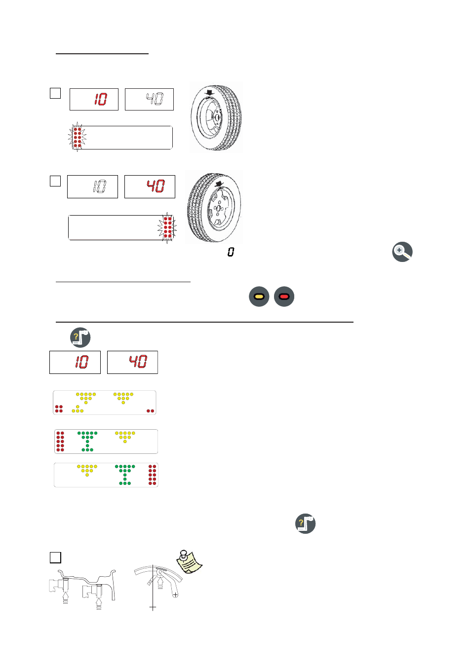
5.3 - Measurement result
After performing a balancing spin, the amounts of unbalance are shown on the digital readouts. The illuminated LEDs
3 and 4 indicate the correct angular position of the wheel to mount the counterweights (12 o’clock).
F
ig. 7a - Inside correction
Fig. 7b - Outside correction
►
Fit the correction weight in the specifi c gauge seat with the adhesive part
facing
upwards
Bring the wheel into correct angular position for the plane to be corrected
withdraw the gauge until the correction plane indication arrows turn green
INSIDE CORRECTION POSITION
OUTSIDE CORRECTION POSITION
Rotate the gauge until the correction weight adheres to the rim
the fact that the weight application position is no longer vertical (Fig. 8) is
automatically
compensated
to cancel this function, press button
again
N.B. : It is not possible to put automatically the correction
weight in the Fig.5/B position; ALWAYS rotate the rim in
Fig.5/A
upwards.
▪
▪
▪
▪
▪
▪
▪
▪
If the unbalance is less than the threshold value selected, is displayed instead of the unbalance value; with
the values below the threshold can be read.
5.4 - Recalculation of the unbalance
Automatic on varying the correction type set-up with the buttons
.
5.5 - Exact positioning of the adhesive weight by means of the gauge with clips
- press
►
►