5 control of serial output rs232c (option) – CEMB USA C65 (E) User Manual
Page 23
I 0206 - 23
GB
7.4.2 - WHEEL BALANCER CALIBRATION
For calibration of the machine, proceed as follows:
- Use a medium-sized metal wheel. Example: 6” x 14” (± 1”)
- Preset the wheel dimensions with GREAT CARE.
- Follow the instructions appearing on the monitor.
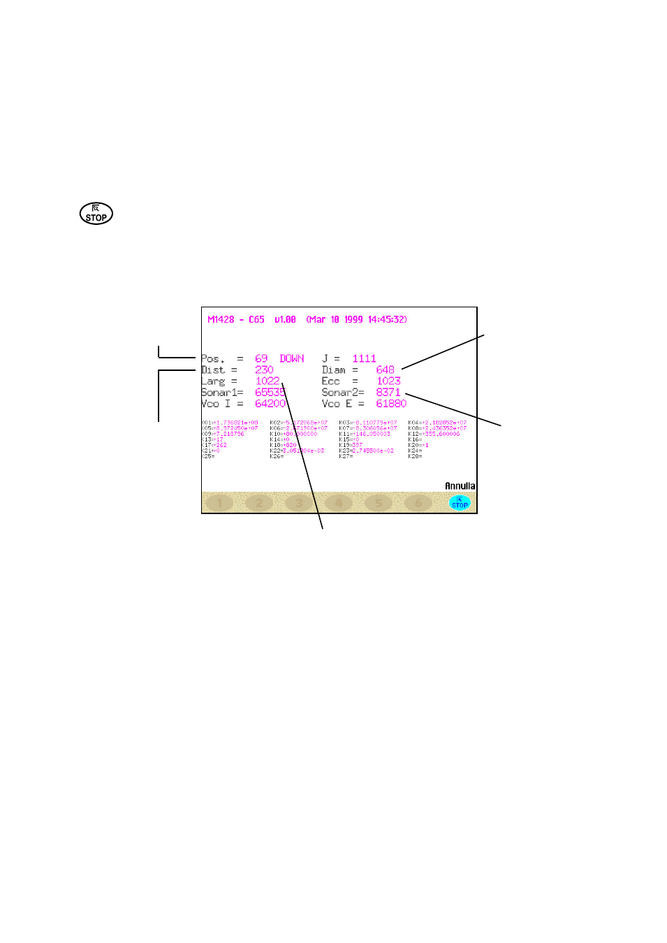
7.4.3 - SELF-DIAGNOSTIC WHEEL BALANCING MACHINE
An automatic self-diagnostics cycle is provided for easier trouble shooting. At the end of the self-
diagnostics cycle, several parameters are displayed which are useful for the Technical Service Depart-
ment in order to identify machine faults.
Returns to previous menu.
7.4.3.1 - TO CHECK THE ENCODER
When the spindle is rotated:
- the angular position “POS” should vary from 0 to 128;
- the wording “UP” should appear when rotated clockwise and “DOWN” when rotated in the opposite
direction.
Encoder check
Check for correct
operation of the
distance gauge;
the number increa-
ses when the gauge
is pulled out.
Check for correct ope-
ration of the diameter
gauge; the number
increases when the
gauge is rotated
outwards
Check of the width
sonar (option): the
number decreases
when a surface is
approached to the
sonar.
Check of the eccentricity sonar (option): the number
decreases when a surface is approached to the
sonar.
In the event of failure or faulty operation of the wheel balancing machine, notify the Technical Service
of all the parameters displayed.
7.5 CONTROL OF SERIAL OUTPUT RS232C (OPTION)
This option enables/disables the sending of the measured unbalance and phase values to serial output
RS232C.
Transmission speed
= 9600 baud
Data format
= 7 bit Start
7 bit Data
1 bit Even parity
1 bit Stop
At the end of each unbalancing measuring spin, the balancing machine enables the RTS signal, then
places the “$” character on standby to be able to transmit the data; all functions remain on hold until data
transmission is enabled, at the end of which the RTS signal is reset to the inactive state.
The items of data transmitted via serial line are in ASCII format and are separated between each other
by the
Sending sequence is as follows:
- 0000
- Value of correction weight, left side
- Correction phase, left side
- Value of correction weight, right side
- Correction phase, right side
The first 5 zero bytes represents the start of transmission message. The correction values are expressed
in grams, in steps of .1 gram. The phase values are expressed in degrees, in the range 0% 359.