Special calibrations and functions – CEMB USA C73-L SE (B) User Manual
Page 22
22
Use and maintenance manual Rev. 10-2009
ENGLISH
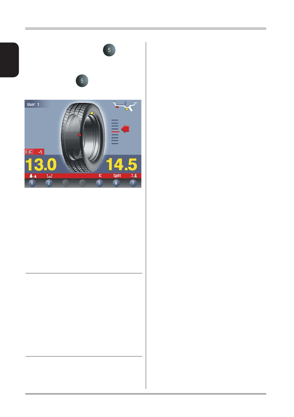
If a special icon appears near the button
, it means that
the wheel balancer is suggesting static balancing,
however, such that also the dynamic torque unbalance will
be brought within tolerance.
When pressing the button
, the position repeater frame
is accessed which clearly indicates where the weight
should be positioned in the rim.
7.10
b
FOR I.C.
In the case of the I.C. correction method, when this function
is set to ON it allows:
displaying the unbalance correction values with an
▪
approximation of 1g/0.1 ounce;
enable the graphic display of the residual static un-
▪
balance and torque as the distance and the diameter
change;
Given the complexity of the information provided to the user,
it is recommended to set this function to ON only on
explicit request and when the wheel balancer is used by
expert personnel.
INDICATION
The innovative IC software has been designed to reduce
the amount of weight used to correct the
unbalance, leaving a residual unbalance on the wheel
within the set tolerances.
The tolerance used by the machine is obtained from a
tolerance of a reference wheel, modified in order to
make the vibration generated by the reference wheel
comparable with that in use.
This is obtained according to the coded theory
of the ISO standards.
In general, a wheel balanced using IC has a higher
residual unbalance than a wheel balanced at best using
the conventional method, but, although generating a
tolerable vibration from the vehicle, it has the
advantage of considerably reducing the counterweights
used.
8.
Special calibrations
and functions
In order to gain access to the “Reserved Calibrations and
functions” it is necessary to enter a password.
Any incorrect operation within the functions described below
could impair the operation of the wheel balancing machine.
Unauthorized use will cause cancellation of the warranty on
the machine.
8.1 OPTIONS
8.1.1 Enabling of width measurement
This function enables/disables automatic width measurement
with SONAR or contact device; always select “SONAR”.
8.1.2 Enabling of eccentricity measurement
Enables/disables measurement of the tyre eccentricity during
an unbalance measurement spin.
8.1.3 Control of serial output RS232C
This opt
ion enables/disables the sending of the measured
unbalance and phase values to serial output RS232C.
Transmission speed
= 9600 baud
Data format
= 7 bit Start
7 bit Data
1
bit
Even
parity
1 bit Stop
At the end of each unbalancing measuring spin, the balancing
machine enables the RTS signal, then places the “$” character
on standby to be able to transmit the data; all functions remain
on hold until data transmission is enabled, at the end of which
the RTS signal is reset to the inactive state.
The items of data transmitted via serial line are in ASCII
format and are separated between each other by the
character (0x0d).
Sending sequence is as follows:
- 00000
- Value of correction weight, left side
- Correction phase, left side
- Value of correction weight, right side
- Correction phase, right side
message. The correction values are expressed in grams, in
steps of .1 gram. The phase values are expressed in degrees,
in the range 0 ÷ 359.
See specifi c computer board on exploded drawings.
Special calibrations and functions