1 presetting of tolerance on the machine, 3 value of unbalance corresponding to eccentricity, 6 eccentricity measurement (optional) – CEMB USA C73-L SE (B) User Manual
Page 17
17
A
B
Use and maintenance manual Rev. 10-2009
ENGLISH
SOLUTION: Rotate the tyre on the rim by 180°
RESULT: no improvement is obtained.
5.5.1 Presetting of tolerance on the
machine
There is no general rule concerning acceptability of an eccen-
tricity value . As a fi rst approximation we consider it correct
to use a threshold of 1 to 1.5 mm. The E/ECE/324 standard
prescribes 1.5 mm as max. eccentricity of a rebuilt tyre.
5.5.2 Value of static unbalance, correlated
with eccentricity
Clear indication is given in the Measurement screen of both
the value and position of the static unbalance as well as the
eccentricity. In fact, it is interesting to check the correlations
of the two values, above all of the two positions. When the
two positions have a similar angle (± 30° one from the other),
there is a clear sign that an eccentricity is present which
can be compensated by matching.
5.5.3 Value of unbalance corresponding to
eccentricity
For user’s reference, the centrifugal force is calculated corre-
sponding to a certain speed, compared to the force generated
by the eccentricity present on the tyre (calculated with an
approximate average elastic constant).
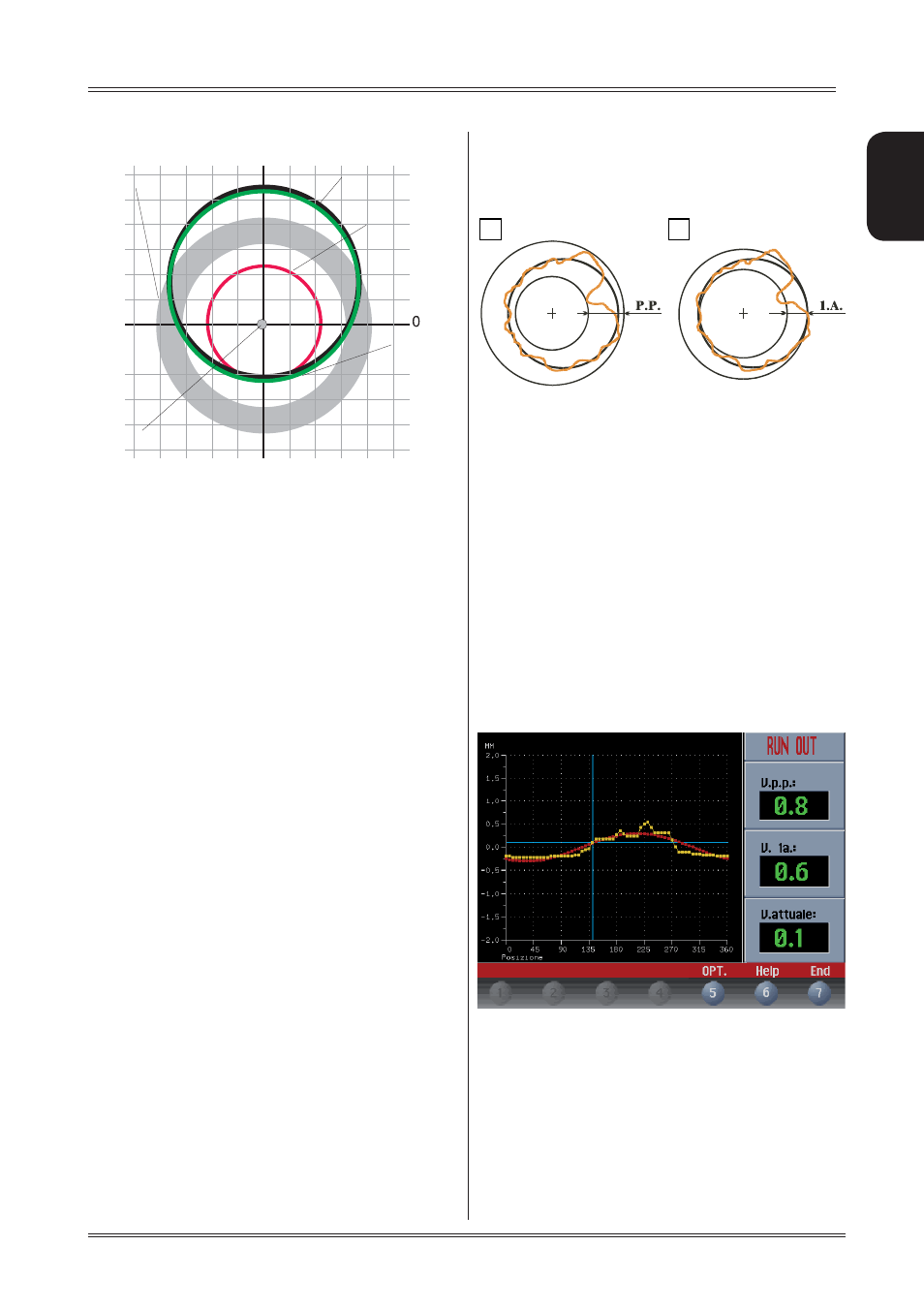
5.6 ECCENTRICITY MEASUREMENT
(OPTIONAL)
The much enlarged fi gures show the outer tyre surface
and axis of wheel rotation.
Fig. A - shows measurement of the total Peak-to-Peak
eccentricity defi ned as maximum radial deviation of the tyre
surface.
Fig. B - shows measurement of the eccentricity of the 1st
harmonic, i.e. the eccentricity of that circle which “recopies”
the tyre shape, by averaging the local deviations of the tyre
from the round shape.
Obviously the P.P. measurement is normally greater than that
of the 1st harmonic. Tyre manufacturers normally supply two
different tolerances for the two eccentricities.
At the end of the balancing spin it is possible to automatically
measure the eccentricity of the tyre through the SONAR sensor
installed on the guard. The sensor should be positioned by
hand in front of the tyre tread.
GRAPH 1 (yellow) : represents the actual Peak-to-Peak
eccentri-city.
GRAPH 2 (red) : represents the eccentricity of the 1st harmo-
nic. For a wheel in optimum conditions, such graph should
approach a straight line.
While rotating the wheel, the screen cursor indicates the
current value, with the stage referred to the eccentricity me-
asurement sensor.
Example 3
Rim 0 mm
Tyre + 1.2 mm
Wheel + 1,2 mm
Eccentricity of the wheel cannot be compensated by the
rotation because the rim is perfect!
wheel
rim
tyre
rotation axle
Ideal wheel
Use of the wheel balancer