A.O. Smith BFC - 28 User Manual
Page 77
is
Release R
.1.3
UK
77
Wa
rn
in
g
Ma
intena
nce may
o
nly be pe
rformed
b
y a
qu
alifie
d se
rvi
ce and main
te
nance
e
ngin
eer
.
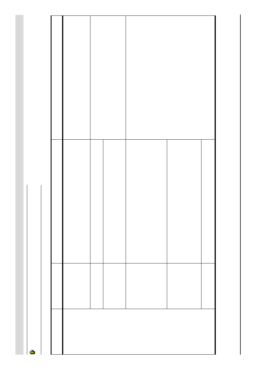
F0
4 (lo
ck ou
t
e
rro
r)
Th
ree unsu
cce
ssful
ignition attempt
s.
No gas.
1.
O
pen
the
mai
n gas valve and
/o
r
the ga
s
val
ve
b
efore th
e gas
control.
2.
C
heck su
ppl
y pre
ssu
re
to the gas control
.
3.
If
necessary
, rep
a
ir the
gas s
u
pply
.
To
rep
air th
e gas suppl
y,
cont
act
yo
ur
in
st
a
ller
.
Ai
r
in
the
g
as
p
ipes.
B
le
ed th
e air out of
the ga
s pi
pe.
Se
e
for
h
ow to
b
lee
d
a
ir from th
e gas lin
e, an
d me
asure the supp
ly
p
ressure and
b
urner pressure
.
To
rep
lace
the
ne
ce
ssary p
a
rt
s, yo
u mu
st
cont
act you
r in
st
al
ler
.
No burne
r
pre
ssu
re.
1.
C
heck the
b
urner
pressure
a
t the gas control.
2.
C
heck tha
t the gas valve
(s) op
en and
shu
t correctly
.
3.
If
n
ecessary
, rep
lace the gas control.
Defect in
the gl
ow
igni
te
r circui
t.
1.
C
heck tha
t the glo
w
igni
te
r is correctly
co
nnected
(JP2).
2.
C
heck the
w
iring of th
e glow
ig
niter
.
3.
Mea
sure th
e re
sist
a
nce across the
g
low ig
niter
. Th
is mu
st lie
b
etween
2
an
d
5
Ω
.
4.
C
heck tha
t the glo
w
igni
te
r li
ght
s
u
p
d
uring
ignitio
n.
5.
If
n
ecessary
, rep
lace the glo
w
igni
ter
.
If the
e
rro
r pe
rsist
s, co
nt
a
ct
your
inst
all
er
.
To
rep
lace
the
ne
ce
ssary p
a
rt
s, yo
u mu
st
cont
act you
r in
st
al
ler
.
Defect in the
io
nisatio
n
ci
rc
u
it.
1.
C
heck tha
t the ion
isation
rod
is
correctly conne
cte
d (JP2
).
2.
C
heck the
w
iring of th
e ioni
sati
on rod.
3.
Mea
sure the io
nisation
current. T
his must be a min
imum of
1
.5
µA.
4.
If
n
ecessary
, rep
lace the wirin
g.
Su
ppl
y
vol
tag
e
to
o
lo
w
C
h
eck the
suppl
y vo
ltage to the a
ppli
ance. T
his must b
e 230
V
A
C
(+10% -15%).
Ta
ble
10.2
Displ
ayed errors (Shee
t 5 of
1
0)
Co
de
+
De
scrip
tio
n
Po
ss
ib
le
c
aus
e
S
o
lu
tio
n
R
emar
k