5 the control panel, 1 introduction, 2 operating – A.O. Smith BFC - 28 User Manual
Page 43: The control panel, Introduction, Operating, 5the control panel
Introduction
Release R.1.3 UK
43
gis
5
The control panel
5.1
Introduction
Topics covered in this chapter:
•
;
•
;
•
5.4 ON/OFF switch of ThermoControl
•
•
5.2
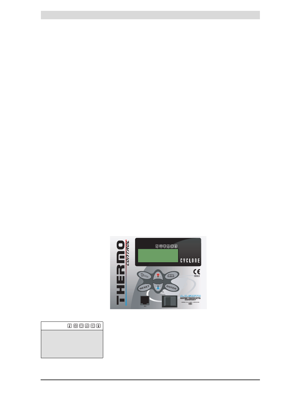
Operating
Figure 5.1
shows the ThermoControl. The control panel is completely menu-
driven. It comprises:
•
a 4-line display with 20 characters per line;
•
6 push buttons for operating the appliance (below the display);
•
6 graphical symbols (above the display);
•
a connector for a service PC;
•
an ON/OFF switch.
The push buttons are divided into three groups:
•
Navigation buttons:
-
Buttons UP H, and DOWN L;
-
Enter: E;
-
Reset button: R
•
The main menu: B (see chapter
•
the service program: S (see chapter
, this chapter is
specifically intended for the service and maintenance engineer and
installer).
In this manual, the display of the ThermoControl is shown as in
with and without icons.
Figure 5.1 ThermoControl
I
0
MENU
»OFF
^ ON
» WEEK PROGRAM
^»START OPERATION
È CHANGE SETPOINT
Tset=70ÉC
Figure 5.2 The display
gis