Figure 3.3 – A.O. Smith BFC - 28 User Manual
Page 24
Installation
24
Instruction Manual BFC
3
is
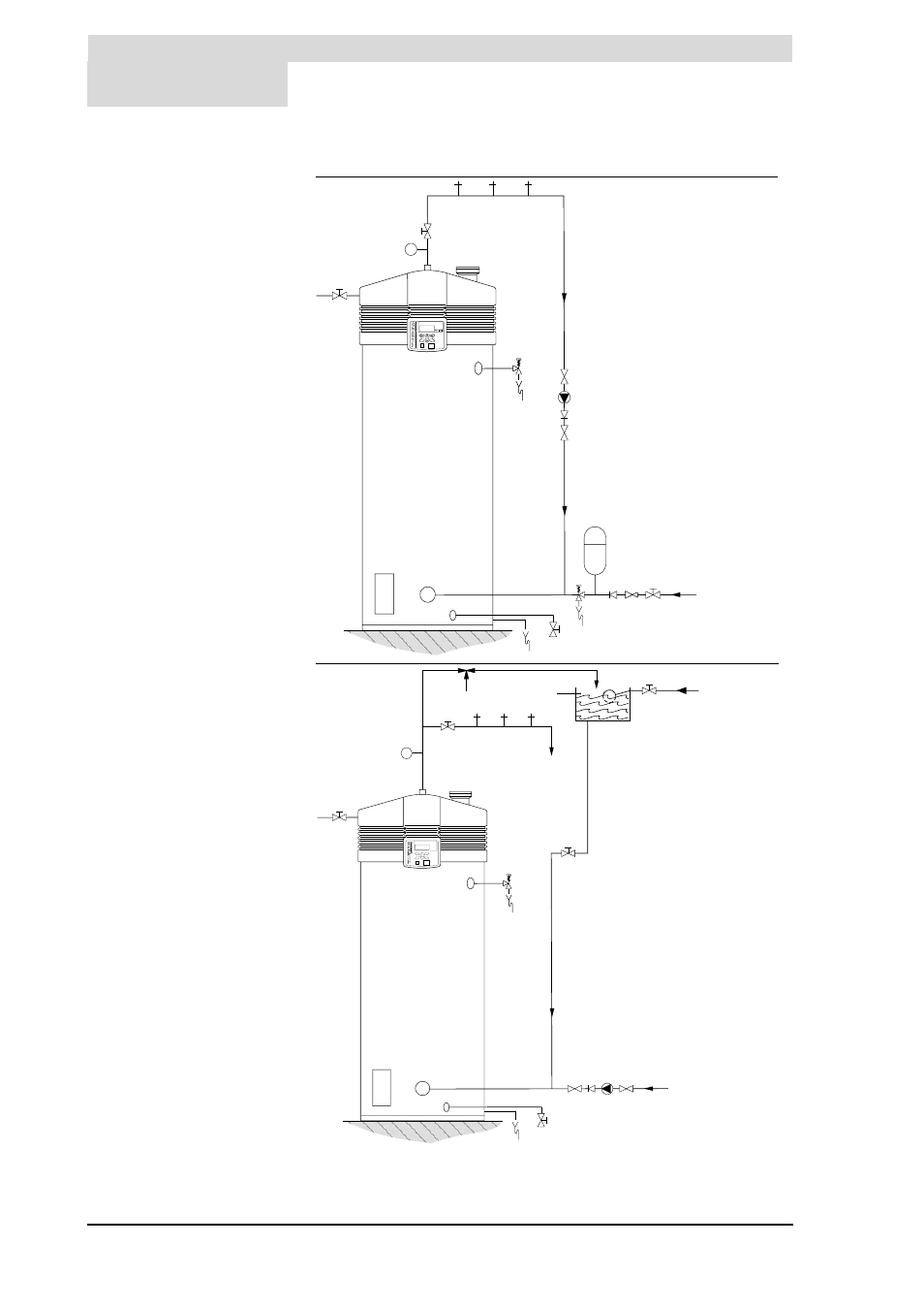
Legend
a
pressure-reducing valve
(mandatory)
b
expansion vessel (mandatory)
c
T&P valve (mandatory)
d
stop valve (recommended)
e
non-return valve (mandatory)
f
circulation pump (optional)
g
drain valve
h
gas valve (mandatory)
i
stop valve (mandatory)
j
temperature gauge (optional)
k
condensation drainage
(mandatory)
l
hot water draw-off points
m
pressure relief valve
(mandatory)
n
water cistern
o
float valve
p
3-way venting valve
(recommended)
q
overflow pipe
a cold water supply
b hot water outlet
c circulation pipe
d gas supply
e flue gas discharge and air
supply
Figure 3.3 Installation diagrams
RE
SE
T
EN
TE
R
T
l
a
c
b
d
h
m
g
d
IMD-0139
e
f
d
e
k
UNVENTED
T
l
a
c
b
d
h
k
g
d
e f
d
q
c
p
o
IMD-0138
VENTED
a
n