3 draining the appliance, 1 draining unvented installations, 2 draining vented installations – A.O. Smith BFC - 28 User Manual
Page 41: Draining the appliance 4.3.1, Draining unvented installations, Draining vented installations
Draining the appliance
Release R.1.3 UK
41
gis
4.3
Draining the
appliance
4.3.1
Draining unvented installations
Some service activities require the appliance to be drained. The procedure is as
follows:
1. Activate the
MENU
with B.
2. Use H and L to place the cursor beside
OFF
. See
Figure 4.2
.
3. Confirm
OFF
with E.
4. Wait until the fan has stopped. The
S
icon is then dimmed.
c
Note
Failure to wait until the fan stops can cause damage to the appliance.
5. Turn the appliance OFF (position 0) using the ON/OFF switch on the
control panel. See
Figure 4.3
.
6. Disconnect the appliance by putting the mains switch between the appliance
and the mains power supply to position 0.
7. Shut off the gas supply h.
8. Close the stop valve i in the hot water pipe.
9. Close the supply valve of the cold water supply a.
10. Open the drain valve g.
11. Bleed the appliance (or installation) so that it drains completely empty.
4.3.2
Draining vented installations
Some service activities require the appliance to be drained. The procedure is as
follows:
1. Activate the
MENU
with B.
2. Use H and L to place the cursor beside
OFF
. See
Figure 4.2
.
3. Confirm
OFF
with E.
4. Wait until the fan has stopped. The
S
icon is then dimmed.
c
Note
Failure to wait until the fan stops can cause damage to the appliance.
5. Turn the appliance OFF (position 0) using the ON/OFF switch on the
control panel. See
Figure 4.3
.
6. Disconnect the appliance by putting the mains switch between the appliance
and the mains power supply to position 0.
7. Shut off the gas supply h.
8. Close the stop valve i in the hot water pipe.
9. Close the stop valve between the water cistern and the cold water inlet.
10. Open the drain valve g.
11. Bleed the appliance (or installation) so that it drains completely empty.
MENU
»OFF
^ ON
È WEEK PROGRAM
Figure 4.2 Main menu
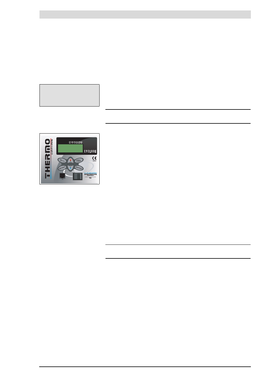
Figure 4.3 ThermoControl
0
I